- ProduitÉquipementPrécision de Puissance, Personnalisation, Solution de GruesCourriel :WhatsApp / Wechat :+8613781917315Adresse :Rue Shanhai n° 18, ville de Changyuan, province du Henan, Chine


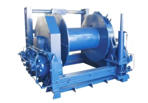
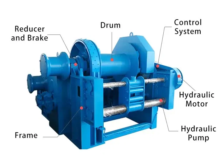
Un treuil hydraulique est un dispositif mécanique motorisé qui convertit l'énergie hydraulique en force de rotation pour enrouler un câble en acier sur un tambour, générant ainsi la force de traction ou de levage nécessaire au déplacement, à l'ancrage ou au positionnement de charges lourdes. Le moteur hydraulique est alimenté en fluide sous pression par une centrale hydraulique externe ou par le système hydraulique de la machine hôte, ce qui élimine le besoin d'une alimentation électrique séparée au niveau du treuil.
Les caractéristiques essentielles d'un treuil hydraulique, comparé à un treuil électrique de capacité nominale équivalente, sont sa capacité à fonctionner à couple maximal dès l'arrêt, à supporter des cycles de service continus sans surchauffe, à maintenir un contrôle précis à très basse vitesse et à se bloquer en toute sécurité en cas de surcharge sans dommage mécanique. Ces propriétés font du treuil hydraulique la solution de référence pour l'amarrage et la manutention d'ancres en mer, les opérations sur les plateformes offshore, le transport minier, la pose de canalisations pétrolières et les travaux de construction lourde dans des environnements où l'alimentation électrique est indisponible, peu fiable ou insuffisante.
Le terme « treuils hydrauliques » désigne l'ensemble de la gamme de produits couvrant toutes les capacités, configurations de montage et applications. Qu'il s'agisse d'un treuil d'amarrage compact de 1 tonne ou d'un treuil de remorquage offshore de 100 tonnes, le principe de fonctionnement de base – un moteur hydraulique entraînant un tambour d'engrenages via un frein de sécurité – reste le même pour toute la gamme de treuils hydrauliques proposée par [Nom du fabricant]. Weihua.
Les treuils hydrauliques Weihua sont classés selon la structure de leur tambour. Le choix de la configuration appropriée dépend du nombre de brins de câble indépendants nécessaires, de la nécessité d'un levage synchronisé et de la capacité de charge totale de l'application.
Un treuil hydraulique à tambour unique utilise un tambour entraîné par un moteur hydraulique pour enrouler et dérouler un câble métallique unique lors d'opérations de levage ou de traction. Sa structure est simple, ses commandes intuitives et son installation et sa maintenance aisées. Les treuils hydrauliques à tambour unique couvrent toute la gamme de capacités, de 1 à 100 tonnes, et constituent la configuration standard pour la plupart des applications de traction dans les secteurs maritime, de la construction, minier et industriel.
Applications typiques : Amarrage et manutention d'ancres de navires, traction sur chantier de construction, halage par arbre incliné, treuils de pont offshore, pose de pipelines et de câbles.
Un treuil hydraulique à double tambour est équipé de deux systèmes de tambours indépendants ou reliés mécaniquement, chacun entraîné par son propre moteur hydraulique ou par un entraînement commun avec embrayage de séparation. Les deux tambours peuvent fonctionner de manière synchrone – pour le levage équilibré d'une charge unique sur deux câbles – ou indépendamment, contrôlant simultanément deux charges ou trajectoires de câbles distinctes. Comparé à une configuration à tambour unique, le treuil hydraulique à double tambour offre une capacité de levage totale supérieure, un équilibrage efficace de la charge sur les points de levage et un contrôle plus précis lors des opérations de levage et de positionnement multipoints.
Applications typiques : Systèmes de levage de grues marines lourdes, manutention d'équipements de plateformes offshore nécessitant un levage équilibré à deux points, systèmes d'amarrage de grands navires avec lignes avant et arrière indépendantes, opérations de pose de câbles synchronisées.
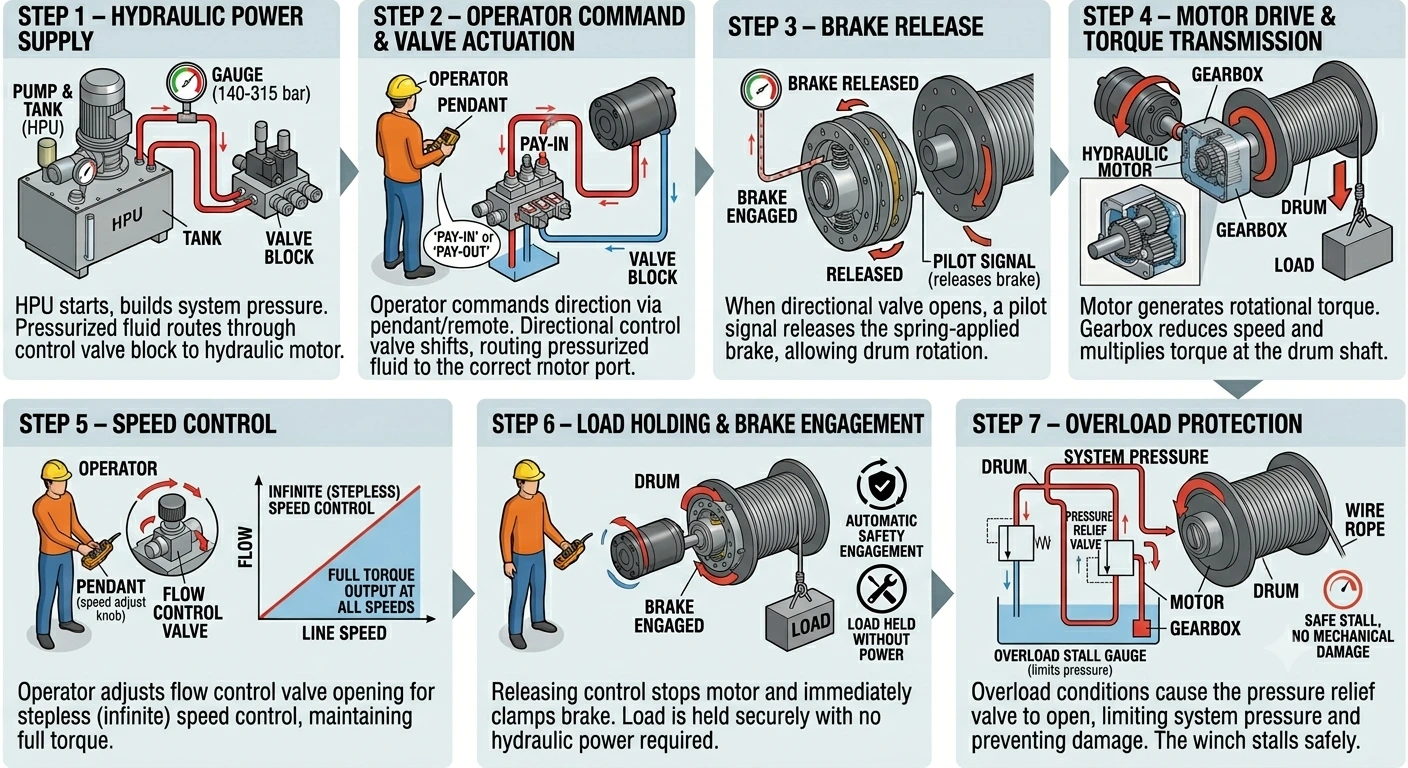
Étape 1 — Alimentation hydraulique Le groupe hydraulique démarre et met le système sous pression jusqu'à la pression de service spécifiée pour le modèle de treuil (140 à 315 bars selon la capacité). Le fluide hydraulique sous pression est acheminé par le bloc de distributeurs vers le moteur hydraulique.
Étape 2 — Commande de l'opérateur et actionnement de la vanne L'opérateur commande l'enroulement (bobinage) ou le déroulement (déroulement) du tambour via la commande pendante ou le système de télécommande. Le distributeur situé dans le bloc de vannes s'inverse, acheminant le fluide sous pression vers l'orifice approprié du moteur hydraulique et renvoyant le fluide basse pression vers le réservoir.
Étape 3 — Relâchement des freins Lorsque le distributeur s'ouvre et que la pression du système augmente, un signal pilote libère le frein à ressort, permettant ainsi la rotation du tambour. Le frein reste relâché tant que l'opérateur maintient la commande et que la pression du système est maintenue.
Étape 4 — Entraînement du moteur et transmission du couple Un fluide haute pression actionne le moteur hydraulique, générant un couple de rotation. Le réducteur diminue la vitesse du moteur et multiplie le couple au niveau de l'arbre du tambour, fournissant ainsi la force de traction nécessaire pour enrouler le câble et lever ou tirer la charge nominale à la vitesse spécifiée.
Étape 5 — Contrôle de la vitesse L'opérateur ajuste l'ouverture du distributeur hydraulique pour moduler le débit d'huile hydraulique vers le moteur, permettant ainsi une variation continue de la vitesse, de quasi-zéro à la vitesse maximale du câble. Contrairement à un treuil électrique, qui nécessite un variateur de fréquence pour la régulation de vitesse, le treuil hydraulique assure une variation continue grâce au seul distributeur hydraulique, maintenant ainsi un couple maximal à toutes les vitesses, même les plus basses.
Étape 6 — Maintien de la charge et engagement des freins Lorsque l'opérateur relâche la commande, le distributeur se ferme, la rotation du moteur s'arrête et le frein à ressort bloque immédiatement le tambour. La charge est maintenue fermement dans sa position, sans dérive, et aucune puissance hydraulique n'est requise pour ce maintien. En cas de perte de pression hydraulique, le frein s'enclenche automatiquement et la charge reste immobilisée.
Étape 7 — Protection contre les surcharges Si la tension du câble dépasse la capacité de traction nominale du treuil (en raison d'une charge coincée ou d'une résistance inattendue), la soupape de décharge du circuit hydraulique s'ouvre, limitant la pression du système et évitant d'endommager le moteur, le réducteur, le tambour et le câble. Le treuil s'arrête en toute sécurité, sans surchauffe ni panne mécanique, un avantage majeur par rapport aux treuils électriques en cas de surcharge.
| Capacité (t) | Traction de ligne (kN) | Diamètre du câble métallique (mm) | Capacité du tambour (m) | Pression de service (bar) | Vitesse de ligne (m/min) |
|---|---|---|---|---|---|
| 1 – 2 | 10 – 20 | 12 – 16 | 50 – 100 | 140 – 160 | 15 – 25 |
| 3 – 5 | 30 – 50 | 16 – 22 | 80 – 150 | 160 – 180 | 12 – 20 |
| 8 – 10 | 80 – 100 | 24 – 28 | 100 – 200 | 180 – 200 | 10 – 18 |
| 15 – 20 | 150 – 200 | 28 – 36 | 150 – 300 | 200 – 250 | 8 – 15 |
| 30 – 50 | 300 – 500 | 40 – 52 | 200 – 400 | 250 – 280 | 6 – 12 |
| 60 – 100 | 600 – 1000 | 56 – 76 | 300 – 600 | 280 – 315 | 5 – 10 |
Le choix entre un treuil hydraulique et un treuil électrique dépend de la charge de l'application, de son cycle de service, de l'environnement et de l'infrastructure électrique disponible. Le tableau ci-dessous récapitule les principaux facteurs de décision.
| Facteur | Treuil hydraulique | Treuil électrique |
|---|---|---|
| Système d'entraînement | Moteur hydraulique + groupe hydraulique | Moteur électrique + boîte de vitesses |
| Régulateur de vitesse | Débit variable par vanne de régulation | contacteur à paliers ou variateur de fréquence |
| Couple à vitesse nulle | Couple nominal maximal | Inférieur ; nécessite un variateur de fréquence pour le couple à basse vitesse |
| service continu | Oui, le circuit d'huile dissipe la chaleur | Le cycle de service est limité par la puissance thermique du moteur. |
| Comportement de surcharge | Calage en toute sécurité grâce à la soupape de décharge | Déclenchements ou surchauffes du moteur |
| Type de frein | Actionnement par ressort, déclenchement hydraulique (sécurité intégrée) | Électromagnétique (à ressort en option) |
| Antidéflagrant | Sécurité intrinsèque au niveau de la tête de treuil | Enceinte Ex complète requise au niveau du moteur |
| Besoins en énergie | Alimentation hydraulique (HPU ou système hôte) | alimentation électrique triphasée |
| Stabilité à basse vitesse | Excellent — fluide même à vitesse quasi nulle | Limité sans variateur de fréquence de haute qualité |
| Poids unitaire | Inférieur pour une capacité équivalente | Plus élevé pour une capacité équivalente |
| Entretien | Huile hydraulique, joints, filtres | Composants électriques, enroulements de moteur |
| environnement approprié | Dur, marin, offshore, minier, dangereux | Industrie générale, intérieur |
Pour les applications en milieu industriel intérieur standard, avec une alimentation électrique fiable et des cycles de service modérés, un treuil électrique est souvent le choix le plus simple et le plus économique. Pour les charges lourdes, un fonctionnement continu, les applications marines et offshore, les zones dangereuses ou les environnements sans alimentation électrique, un treuil hydraulique est la solution appropriée.
1. Capacité de traction nominale La capacité de traction nominale d'un treuil hydraulique est spécifiée pour la première couche de câble enroulée sur le tambour. Plus le câble s'enroule sur plusieurs couches, plus le rayon effectif du tambour augmente et plus la force de traction diminue. Si votre application requiert la capacité nominale maximale en bout de câble, veuillez vérifier les performances en configuration multicouche auprès de notre équipe d'ingénieurs et choisir un modèle offrant une capacité suffisante pour la première couche.
2. Diamètre du câble et capacité du tambour Le diamètre du câble doit correspondre à sa capacité de traction nominale et à sa charge de rupture minimale. La capacité du tambour (en mètres) doit être suffisante pour permettre le déroulement complet du câble nécessaire à l'application, y compris les spires mortes retenues sur le tambour après déroulement maximal.
3. Exigence de vitesse de ligne La vitesse de la ligne influe sur la productivité opérationnelle et sur le débit hydraulique requis par le groupe hydraulique. Plus la vitesse est élevée, plus le débit hydraulique nécessaire est important. Assurez-vous que le groupe hydraulique ou le système hydraulique hôte peut fournir le débit requis à la pression de service du treuil sélectionné.
4. Pression de service et compatibilité avec l'unité de traitement hydraulique Les treuils hydrauliques sont conçus pour fonctionner dans une plage de pression de service spécifique (140–315 bar). Le groupe hydraulique doit fournir une pression comprise dans cette plage, au débit requis. Si vous prévoyez d'intégrer le treuil au système hydraulique d'une machine existante, assurez-vous, avant de passer commande, que la pression et le débit disponibles du système sont compatibles avec les spécifications du treuil.
5. Configuration de montage Les treuils hydrauliques sont disponibles en versions à embase horizontale, à bride et à tambour vertical. Avant de choisir le mode de montage, vérifiez l'espace disponible, la capacité de charge du pont et le sens de guidage du câble.
6. Exigences de certification Les applications marines requièrent une certification de société de classification (ABS, CCS, DNV, BV ou LR selon l'État du pavillon du navire). Les applications offshore et en zones dangereuses peuvent exiger une certification antidéflagrante ATEX ou IECEx pour le groupe hydraulique et le système de contrôle. Les applications minières requièrent une certification de sécurité minière. Veuillez préciser les certifications requises lors de votre demande afin de garantir la fourniture de la documentation adéquate à la livraison.
| Certification / Norme | Couverture |
|---|---|
| Marquage CE | Conformité européenne — Directive Machines 2006/42/CE |
| ISO 9001 | Système de gestion de la qualité |
| ABS (Bureau américain de la navigation) | Marine et offshore — navires battant pavillon américain et international |
| CCS (Société de classification chinoise) | Secteur maritime et offshore — Navires battant pavillon chinois et marché intérieur |
| DNV (Det Norske Veritas) | Marine et offshore — navires battant pavillon norvégien et international |
| BV (Bureau Veritas) | Marine et offshore — navires battant pavillon français et international |
| LR (Registre de Lloyd) | Secteur maritime et offshore — navires battant pavillon britannique et international |
| ATEX / IECEx | Groupe hydraulique antidéflagrant et commandes pour zones dangereuses 1 et 2 |
| Certificat de sécurité minière | applications dans l'exploitation minière souterraine et l'industrie du charbon |
La certification de classification et la certification antidéflagrante sont disponibles sur demande pour les modèles concernés. La documentation de certification est fournie à la livraison et permet de réaliser des inspections de classe de navire, des audits de conformité des installations et des contrôles réglementaires.
Weihua est un fabricant et fournisseur professionnel de treuils hydrauliques basé en Chine, fort de plus de 37 ans d'expérience dans la conception et la fabrication d'équipements de levage et de traction. Tous les treuils hydrauliques Weihua sont produits selon un système de gestion de la qualité rigoureux et certifié. ISO 9001, et chaque unité est marquée CE conformément à la directive européenne sur les machines.
Weihua propose un réseau mondial de service après-vente, une garantie produit d'un an et une disponibilité à long terme des pièces détachées pour tous ses modèles de treuils hydrauliques. Notre équipe d'ingénieurs prend en charge la conception de treuils sur mesure, l'intégration de systèmes hydrauliques, ainsi que l'installation et la mise en service sur site pour des projets maritimes, offshore, miniers et de construction dans le monde entier.
Nous proposons également une gamme complète d'équipements de levage et de manutention, incluant des treuils électriques, des ponts roulants, des portiques et des palans à câble. Contactez notre équipe d'ingénieurs dès aujourd'hui pour une solution de treuil hydraulique sur mesure, ou consultez notre gamme complète de treuils hydrauliques disponibles et demandez un devis directement.
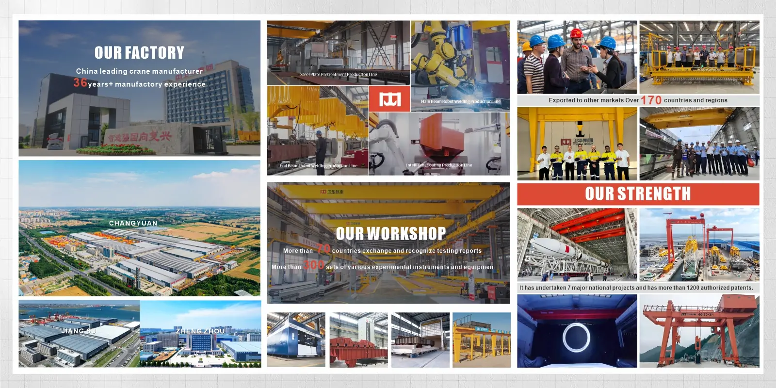
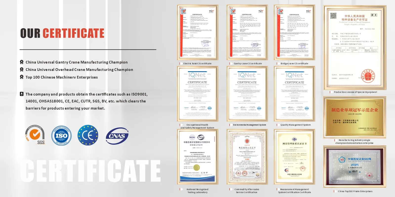
Fondée en 1988, Weihua est devenue un leader mondial dans le domaine de la fabrication intelligente en Chine. Nous sommes spécialisés dans la R&D et la production de grues intelligentes tout en proposant des solutions d'AGV. Nos équipes professionnelles d'ingénierie, de livraison et d'après-vente offrent un support technique complet, des solutions personnalisées, des conseils d'installation sur site et des services mondiaux à réponse rapide pour garantir que chaque projet fonctionne en toute sécurité et efficacité.
Un treuil hydraulique est un dispositif de traction motorisé qui utilise un fluide hydraulique sous pression pour actionner un moteur. Ce dernier fait tourner un tambour afin d'enrouler et de dérouler un câble en acier. Le câble transmet la force de traction ou de levage à la charge. Les treuils hydrauliques sont utilisés pour déplacer, lever, ancrer ou positionner des charges lourdes dans des environnements industriels, maritimes, miniers ou de construction exigeants.
Un treuil hydraulique est actionné par un fluide hydraulique sous pression provenant d'une centrale hydraulique ou du système hydraulique de la machine hôte. Un treuil électrique est alimenté par un réseau électrique triphasé. Les treuils hydrauliques offrent un couple plus élevé, un meilleur contrôle à basse vitesse, une capacité de fonctionnement continu et une protection intrinsèque contre les explosions au niveau de la tête de treuil. Les treuils électriques sont plus simples à installer là où l'alimentation électrique est fiable et où les cycles de service sont modérés. Pour les applications exigeantes, continues ou en zones dangereuses, un treuil hydraulique est le choix idéal.
Un groupe hydraulique alimente en fluide sous pression un moteur hydraulique monté sur le treuil. Ce moteur convertit la pression du fluide en couple de rotation, lequel est transmis par un réducteur au tambour d'enroulement du câble. La rotation du tambour entraîne l'enroulement ou le déroulement du câble, générant ainsi une force de traction ou de levage. Un frein à ressort bloque automatiquement le tambour dès que le circuit hydraulique est dépressurisé ou que l'opérateur relâche la commande, maintenant ainsi la charge dans n'importe quelle position en l'absence de puissance hydraulique.
La pression de service dépend du modèle et de la capacité nominale du treuil. Les treuils hydrauliques Weihua fonctionnent entre 140 bars (pour les modèles de 1 à 2 tonnes) et 315 bars (pour les modèles de 60 à 100 tonnes). Le groupe hydraulique doit fournir la pression de service spécifiée au débit requis pour la vitesse de câble sélectionnée.
Un treuil hydraulique ne comporte aucun composant électrique au niveau de son corps. De ce fait, il est intrinsèquement compatible avec les environnements explosifs, puisqu'il n'y a ni arc électrique ni source de chaleur à proximité du treuil. Pour les zones classées 1 ou 2, le groupe hydraulique et le système de commande doivent être certifiés ATEX ou IECEx. Cette solution est plus simple et moins coûteuse que la certification d'un treuil et d'un moteur entièrement électriques pour une utilisation en zone antidéflagrante.
Contactez-nous dès maintenant par e-mail : [email protected], ou remplissez le formulaire ci-dessous.


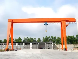
La potence est un équipement de levage largement utilisé dans diverses industries, sur les chantiers de construction, dans les ports, les entrepôts et d'autres domaines. Sa structure unique et sa puissante capacité de charge le rendent idéal pour la manutention moderne de matériaux lourds. La conception de la structure “potence” permet à la grue de se déplacer librement dans un espace, couvrant une large zone de travail. Alors, qu'est-ce qui rend les potences spéciales ? Quels sont leurs types, leurs paramètres, leurs méthodes de contrôle, leurs applications et leurs principes de fonctionnement ? En quoi diffèrent-elles des ponts roulants ? Explorons ensemble. Types de potences Basées sur la conception, l'application et l'environnement d'exploitation, les potences sont généralement classées dans les types suivants : Potence à poutre unique Les potences à poutre unique sont largement utilisées dans les secteurs industriels, les entrepôts, les ports et les ateliers. Dotées d'un mécanisme de levage à support à poutre unique, elles se déplacent via des colonnes latérales et des rails au sol. Avec leur structure simple, leur fonctionnement convivial et leur capacité de levage modérée, elles sont idéales pour la manutention de charges légères à moyennes. Capables de couvrir de grandes distances librement, les potences à poutre unique conviennent aux opérations de manutention et de levage de matériaux lourds. Potence à double poutre Par rapport aux potences à poutre unique, les potences à double poutre offrent une plus grande…
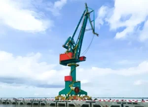
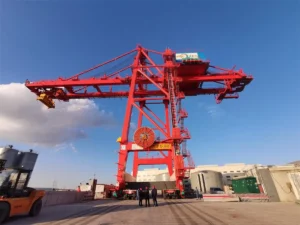
Dans les ports, les parcs logistiques et la manutention de matériaux industriels, les grues à quai et les portiques sont deux types d'équipements de chargement/déchargement courants et essentiels. Ils diffèrent par leur conception structurelle, leurs caractéristiques de performance, leurs méthodes d'exploitation, leurs scénarios d'application et leurs coûts d'investissement. Cet article fournit une analyse complète des grues à quai par rapport aux portiques et vous guide dans le choix approprié. Comparaison de la conception structurelle Les différences structurelles entre les grues à quai et les portiques se manifestent principalement dans les méthodes de support de charge, les trajectoires de mouvement et les plages de couverture. La première est centrée sur une tour fixe et une flèche rotative, mettant l'accent sur la “ couverture ponctuelle ” et la rotation horizontale flexible. La seconde présente une structure en portique et un déplacement longitudinal sur rails, privilégiant le “ vaste mouvement horizontal ” et la manutention logistique efficace sur site. Par conséquent, leurs conceptions structurelles distinctes dictent directement leurs différents scénarios d'application. Caractéristiques structurelles de la grue à quai Les grues à rotation de portique utilisent des structures de flèche cantilever simple/double avec la tour fixée à des fondations ou à des rails, permettant une rotation à 360° ou partielle. Cette configuration permet une opération flexible dans des espaces étroits et allongés tels que les rives, les fronts de quai et les postes de navire, ce qui la rend particulièrement adaptée à la manutention de matériaux du navire à terre. Sa fonctionnalité principale combine verticalement…
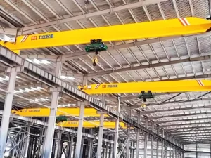
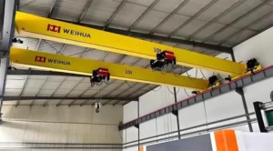
Dans les opérations industrielles modernes, la manutention efficace des matériaux est essentielle pour maximiser la productivité et optimiser le flux de travail. Les ponts roulants, également connus sous le nom de grues aériennes ou de grues EOT, sont des systèmes de manutention fixes largement utilisés dans les secteurs de la fabrication, du traitement des métaux, de l'entreposage et des opérations de chargement/déchargement. Dans cet article, nous explorerons le principe de fonctionnement, les composants principaux, les applications et les avantages opérationnels des ponts roulants, offrant ainsi un guide complet pour les planificateurs industriels et les professionnels de la logistique. Principe de fonctionnement d'un pont roulant Un pont roulant fonctionne sur une structure semblable à un pont qui enjambe l'espace de travail, avec un chariot et un système de levage qui se déplacent horizontalement le long du pont et soulèvent ou abaissent verticalement les charges. Le déplacement de la grue le long du chemin de roulement, combiné à un contrôle précis du palan, permet une manutention efficace et sûre des matériaux lourds dans les usines, les entrepôts et les installations industrielles. Pour plus d'informations sur le fonctionnement des grues aériennes, veuillez consulter cet article : Principe de fonctionnement des grues aériennes : composants, mouvement et processus d'exploitation Terminologie des ponts roulants Voici une introduction à la terminologie relative aux pièces des ponts roulants. Capacité de la grue : La capacité de la grue fait référence au poids maximum qu'un pont roulant peut soulever en toute sécurité. Généralement mesurée en tonnes…
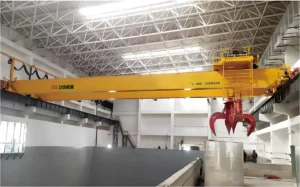
Une grue EOT (Electric Overhead Traveling Crane) est un système de levage aérien efficace et fiable utilisé pour manipuler des matériaux lourds dans les usines, les entrepôts, les ateliers et les installations industrielles. Fonctionnant sur des rails aériens, les grues EOT permettent un mouvement tridimensionnel sûr et précis des charges grâce à des mouvements coordonnés de levage, de translation et de pontage. Cet article vous guidera à travers les définitions des grues EOT, leurs types, leur structure, leurs principes de fonctionnement, leurs applications et les facteurs de coût afin de vous aider à choisir la solution la plus adaptée à vos besoins de levage. Comment fonctionne une grue EOT ? Le principe de fonctionnement d'une grue EOT repose sur une combinaison de levage vertical, de mouvement horizontal du chariot et de déplacement longitudinal du pont, permettant une manipulation efficace de charges lourdes dans les installations industrielles. La grue circule sur des rails de roulement surélevés installés le long de la structure du bâtiment, le pont de la grue enjambant l'espace de travail. Le mécanisme de levage monte ou descend la charge à l'aide de câbles en acier ou de chaînes, tandis que le chariot déplace la charge horizontalement le long du pont. L'ensemble de la grue se déplace longitudinalement le long des rails de roulement, permettant un positionnement tridimensionnel des matériaux. Les grues EOT modernes sont alimentées par des moteurs électriques à vitesse précise…
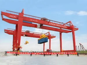
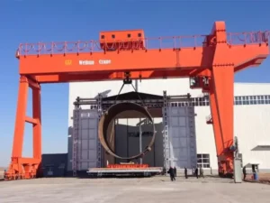
Les portiques sont largement utilisés dans les parcs à matériaux en plein air, les chantiers navals, les usines et les sites de construction, ce qui en fait l'une des solutions de manutention les plus polyvalentes et les plus appliquées. Les portiques existent en différents types, chacun personnalisable pour s'adapter à différentes capacités de charge, conditions de site et exigences opérationnelles. Cependant, choisir la mauvaise configuration peut entraîner des dépenses inutiles, une capacité de levage limitée ou des contraintes d'expansion futures. Alors, quels sont les principaux types de portiques ? Comment choisir le bon type pour votre application ? Dans ce guide, nous fournir un aperçu détaillé des différents types de portiques en fonction de leur structure, de leur mobilité et des scénarios d'application, vous aidant à prendre la bonne décision avant d'investir dans une solution de levage. L'article est assez long. Ci-dessous se trouve notre table des matières. Veuillez accéder à la section correspondante si nécessaire : Qu'est-ce qu'un portique ? Les portiques sont des équipements de levage conçus pour la manutention efficace de charges lourdes sur de grands sites en plein air. Leur structure caractéristique comprend une ou plusieurs poutres principales supportées par des pieds rigides (ou flexibles) de chaque côté, formant un cadre monumental en forme de “ portail ”. Ces grues se déplacent…
 English English
  Русский
 العربية
 Français
 Português
 Español