- منتجمعداتالدقة الكهربائية، التخصيص، حلول الرافعاتبريد إلكتروني:واتساب / وي شات:+8613781917315عنوانرقم 18 طريق شانهاي، مدينة تشانغ يوان، مقاطعة خنان، الصين


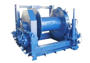
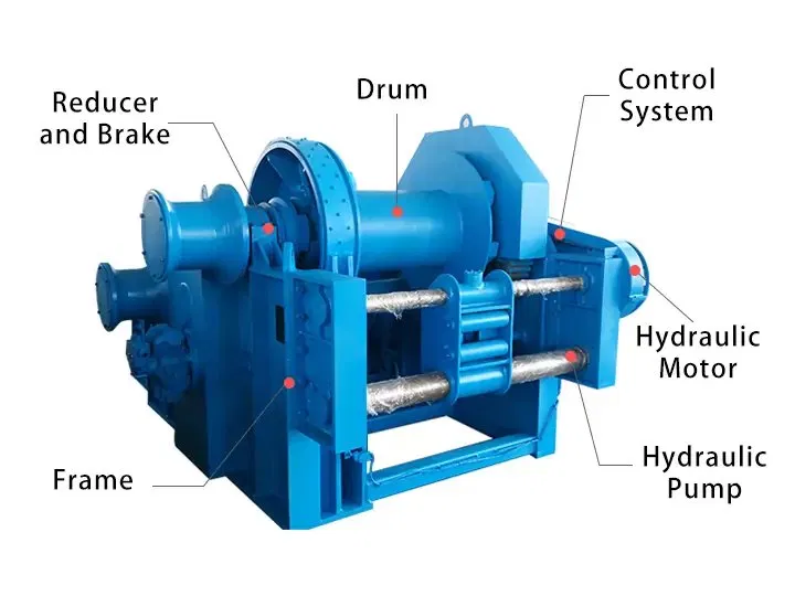
A hydraulic winch is a powered mechanical device that converts hydraulic energy into rotational force to wind a steel wire rope onto a drum, generating the pulling or lifting force required to move, anchor, or position heavy loads. The hydraulic motor receives pressurized fluid from an external hydraulic power unit (HPU) or the host machine’s existing hydraulic system, eliminating the need for a separate electrical power supply at the winch location.
The defining characteristics of a hydraulic winch — compared to an electric winch of equivalent rated capacity — are its ability to operate at full torque from zero speed, sustain continuous duty cycles without overheating, maintain precise control at very low line speeds, and stall safely under overload without mechanical damage. These properties make the hydraulic winch the standard solution for marine mooring and anchor handling, offshore platform operations, mining haulage, oilfield pipe-laying, and heavy construction work where electric power is unavailable, unreliable, or insufficient.
The term hydraulic winches refers to the broader product family covering all capacity ranges, mounting configurations, and application types. Whether the application requires a compact 1 t mooring winch or a 100 t offshore towing winch, the core operating principle — hydraulic motor driving a geared drum through a fail-safe brake — is consistent across the full product range of hydraulic winches available from ويهوا.
Weihua hydraulic winches are classified by drum structure. Selecting the correct configuration depends on the number of independent rope lines required, the need for synchronized lifting, and the total load capacity of the application.
A single-drum hydraulic winch uses one drum driven by a hydraulic motor to wind and unwind a single wire rope for lifting or pulling operations. The overall structure is straightforward, controls are simple, and the unit is easy to install and maintain. Single-drum hydraulic winches cover the full capacity range from 1 t to 100 t and are the standard configuration for the majority of marine, construction, mining, and industrial traction applications.
Typical applications: Ship mooring and anchor handling, construction site pulling, inclined shaft haulage, offshore deck winches, pipeline and cable laying.
A double-drum hydraulic winch is equipped with two independent or mechanically interlinked drum systems, each driven by its own hydraulic motor or by a shared drive with clutch separation. The two drums can operate synchronously — for balanced lifting of a single load across two rope lines — or independently, controlling two separate loads or rope paths simultaneously. Compared to a single-drum configuration, the double-drum hydraulic winch provides greater total lifting capacity, effective load balancing across the lift points, and more precise control in multi-point lifting and positioning operations.
Typical applications: Heavy marine crane hoisting systems, offshore platform equipment handling requiring balanced two-point lift, large ship mooring systems with independent fore and aft lines, synchronized cable-laying operations.
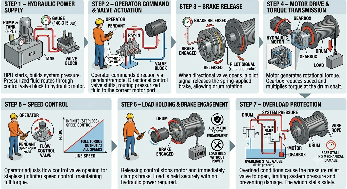
Step 1 — Hydraulic Power Supply The hydraulic power unit starts and builds system pressure to the working pressure specified for the winch model (140–315 bar depending on capacity). Pressurized hydraulic fluid is routed through the control valve block to the hydraulic motor.
Step 2 — Operator Command & Valve Actuation The operator commands pay-in (drum wind) or pay-out (drum unwind) via the pendant control or remote system. The directional control valve in the valve block shifts, routing pressurized fluid to the appropriate port of the hydraulic motor and returning low-pressure fluid to the tank.
Step 3 — Brake Release When the directional valve opens and system pressure builds, a pilot signal releases the spring-applied brake, allowing the drum to rotate. The brake remains released for as long as the operator holds the command and system pressure is maintained.
Step 4 — Motor Drive & Torque Transmission High-pressure fluid drives the hydraulic motor, generating rotational torque. The gearbox reduces motor speed and multiplies torque at the drum shaft, providing the pulling force required to wind the wire rope and lift or pull the rated load at the specified line speed.
Step 5 — Speed Control The operator adjusts the flow control valve opening to vary the hydraulic fluid flow rate to the motor, providing stepless (infinite) speed control from near-zero to maximum line speed. Unlike an electric winch, which requires a variable frequency drive for speed control, the hydraulic winch achieves full stepless control through the hydraulic valve alone, maintaining full torque output at any speed including very low speeds.
Step 6 — Load Holding & Brake Engagement When the operator releases the control, the directional valve closes, motor rotation stops, and the spring-applied brake immediately clamps the drum. The load is held securely at its current position with no drift, and no hydraulic power is required to maintain the hold. In the event of hydraulic pressure loss, the brake engages automatically and the load remains locked.
Step 7 — Overload Protection If the wire rope tension exceeds the winch’s rated pulling capacity — due to a snagged load or unexpected resistance — the pressure relief valve in the hydraulic circuit opens, limiting system pressure and preventing damage to the motor, gearbox, drum, and wire rope. The winch stalls safely without overheating or mechanical failure, a key advantage over electric winches in overload conditions.
| Capacity (t) | Line Pull (kN) | Wire Rope Diameter (mm) | Drum Capacity (m) | Working Pressure (bar) | Line Speed (m/min) |
|---|---|---|---|---|---|
| 1 – 2 | 10 – 20 | 12 – 16 | 50 – 100 | 140 – 160 | 15 – 25 |
| 3 – 5 | 30 – 50 | 16 – 22 | 80 – 150 | 160 – 180 | 12 – 20 |
| 8 – 10 | 80 – 100 | 24 – 28 | 100 – 200 | 180 – 200 | 10 – 18 |
| 15 – 20 | 150 – 200 | 28 – 36 | 150 – 300 | 200 – 250 | 8 – 15 |
| 30 – 50 | 300 – 500 | 40 – 52 | 200 – 400 | 250 – 280 | 6 – 12 |
| 60 – 100 | 600 – 1000 | 56 – 76 | 300 – 600 | 280 – 315 | 5 – 10 |
Choosing between a hydraulic winch and an electric winch depends on the application’s load, duty cycle, environment, and available power infrastructure. The table below covers the primary decision factors.
| عامل | ونش هيدروليكي | Electric Winch |
|---|---|---|
| Drive system | Hydraulic motor + HPU | Electric motor + gearbox |
| Speed control | Stepless via flow control valve | Stepped contactor or VFD |
| Torque at zero speed | Full rated torque | Lower; requires VFD for low-speed torque |
| Continuous duty | Yes — oil circuit dissipates heat | Duty cycle limited by motor thermal rating |
| Overload behavior | Stalls safely via relief valve | Motor trips or overheats |
| Brake type | Spring-applied, hydraulic released (fail-safe) | Electromagnetic (spring-applied optional) |
| Explosion-proof | Intrinsically safe at winch head | Full Ex enclosure required at motor |
| Power requirement | Hydraulic supply (HPU or host system) | 3-phase electrical supply |
| Low-speed stability | Excellent — smooth at near-zero speed | Limited without high-quality VFD |
| وزن الوحدة | Lower for equivalent capacity | Higher for equivalent capacity |
| صيانة | Hydraulic oil, seals, filters | Electrical components, motor windings |
| Suitable environment | Harsh, marine, offshore, mining, hazardous | General industrial, indoor |
For applications in standard indoor industrial environments with reliable electrical supply and moderate duty cycles, an electric winch is often the simpler and more economical choice. For heavy loads, continuous duty, marine and offshore service, hazardous areas, or where electrical power is unavailable, a hydraulic winch is the correct solution.
1. Rated Pulling Capacity The rated pulling capacity of a hydraulic winch is specified at the first layer of rope on the drum. As rope builds up on the drum in multiple layers, the effective drum radius increases and the pulling force decreases. If your application requires the full rated capacity at the end of a long rope run, confirm the multi-layer performance with our engineering team and select a model with sufficient first-layer capacity.
2. Wire Rope Diameter and Drum Capacity Rope diameter must be matched to the rated pulling capacity and the minimum breaking load of the rope selected. Drum capacity (in meters) must be sufficient to cover the full rope travel required by the application, including any dead wraps retained on the drum at maximum pay-out.
3. Line Speed Requirement Line speed affects both operational productivity and the hydraulic flow rate required from the HPU. Higher line speeds require greater hydraulic flow. Confirm that the HPU or host hydraulic system can supply the required flow at the working pressure of the selected winch model.
4. Working Pressure and HPU Compatibility Hydraulic winch models are designed to operate within a specific working pressure range (140–315 bar). The HPU must supply pressure within this range at the required flow rate. If integrating the winch into an existing machine hydraulic system, confirm that system pressure and available flow are compatible with the winch specification before ordering.
5. Mounting Configuration Hydraulic winches are available in base-plate (horizontal), flange-mount, and vertical drum configurations. Confirm the available mounting space, deck loading capacity, and required rope lead direction before specifying the mounting arrangement.
6. Certification Requirements Marine applications require classification society certification (ABS, CCS, DNV, BV, or LR depending on vessel flag state). Offshore and hazardous area applications may require ATEX or IECEx explosion-proof certification for the HPU and control system. Mining applications require Mine Safety Certification. Specify the required certifications at the time of inquiry to ensure the correct documentation is provided with delivery.
| Certification / Standard | Coverage |
|---|---|
| علامة CE | European conformity — Machinery Directive 2006/42/EC |
| ISO 9001 | Quality management system |
| ABS (American Bureau of Shipping) | Marine and offshore — US and international flag vessels |
| CCS (China Classification Society) | Marine and offshore — China flag vessels and domestic market |
| DNV (Det Norske Veritas) | Marine and offshore — Norwegian and international flag vessels |
| BV (Bureau Veritas) | Marine and offshore — French and international flag vessels |
| LR (Lloyd’s Register) | Marine and offshore — UK and international flag vessels |
| ATEX / IECEx | Explosion-proof HPU and controls for Zone 1 / Zone 2 hazardous areas |
| Mine Safety Certificate | Underground mining and coal industry applications |
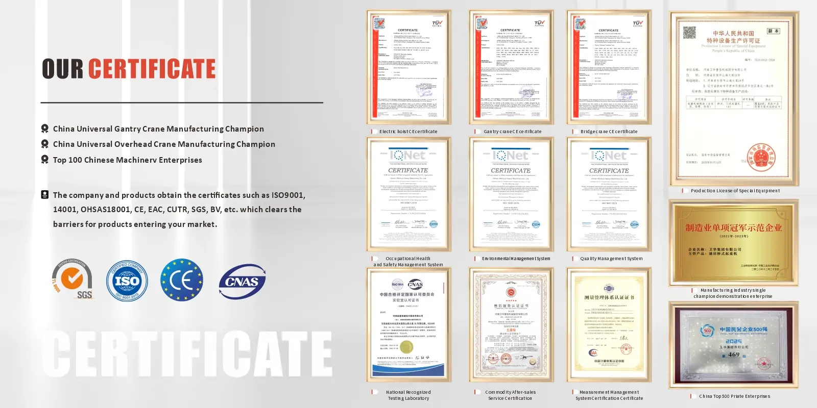
Classification society and explosion-proof certification is available on request for applicable models. Certification documentation is provided with delivery and supports vessel class surveys, facility compliance audits, and regulatory inspections.
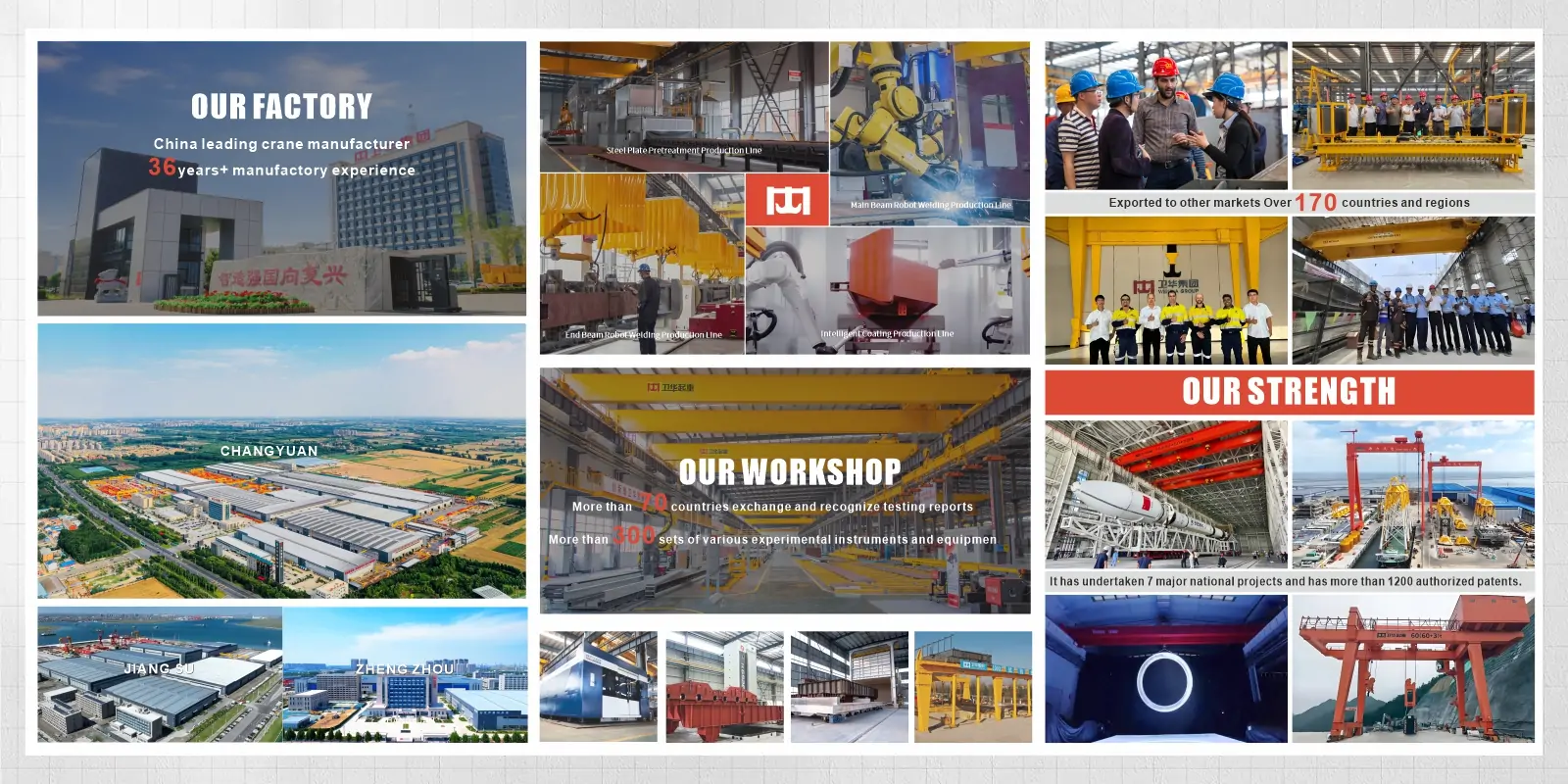
Weihua is a professional hydraulic winch manufacturer and supplier based in China, with over 37 years of experience in lifting and traction equipment design and manufacturing. All Weihua hydraulic winches are produced under a rigorous quality management system certified to ISO 9001, and every unit is CE-marked in compliance with the European Machinery Directive.
Weihua provides a global after-sales service network, a one-year product warranty, and long-term spare parts availability for all hydraulic winch models. Our engineering team supports custom winch specifications, hydraulic system integration, and on-site installation and commissioning for marine, offshore, mining, and construction projects worldwide.
We also offer a comprehensive range of lifting and material handling equipment, including electric winches, overhead cranes, gantry cranes, and wire rope hoists. Contact our engineering team today for a customized hydraulic winch solution — or browse our full range of hydraulic winches for sale and request a quotation directly.
تطورت شركة "وي هوا"، التي تأسست عام 1988، لتصبح رائدة عالمية في مجال التصنيع الذكي في الصين. نحن متخصصون في البحث والتطوير وإنتاج الرافعات الذكية، مع توفير حلول المركبات الموجهة آليًا (AGV). تقدم فرقنا الهندسية والتسليم وما بعد البيع المحترفة دعمًا تقنيًا شاملًا، وحلولًا مخصصة، وإرشادات تركيب في الموقع، وخدمات عالمية سريعة الاستجابة لضمان تشغيل كل مشروع بأمان وكفاءة.
A hydraulic winch is a powered traction device that uses pressurized hydraulic fluid to drive a motor, which rotates a drum to wind and unwind a steel wire rope. The wire rope transmits pulling or lifting force to the load. Hydraulic winches are used wherever heavy loads must be moved, lifted, anchored, or positioned in demanding industrial, marine, mining, or construction environments.
A hydraulic winch is powered by pressurized hydraulic fluid from a hydraulic power unit or host machine hydraulic system. An electric winch is powered by a three-phase electrical supply. Hydraulic winches deliver higher torque, better low-speed control, continuous duty capability, and inherent explosion-proof compatibility at the winch head. Electric winches are simpler to install where reliable electrical power is available and duty cycles are moderate. For heavy, continuous, or hazardous-area applications, a hydraulic winch is the correct choice.
A hydraulic power unit supplies pressurized fluid to a hydraulic motor mounted on the winch. The motor converts fluid pressure into rotational torque, which passes through a gearbox to the wire rope drum. As the drum rotates, the wire rope winds onto or off the drum, generating pulling or lifting force. A spring-applied brake locks the drum automatically whenever the hydraulic circuit is depressurized or the operator releases the control, holding the load at any position without hydraulic power.
Working pressure depends on the winch model and rated capacity. Weihua hydraulic winches operate in the range of 140 bar (for 1–2 t models) to 315 bar (for 60–100 t models). The hydraulic power unit must supply the specified working pressure at the required flow rate for the selected line speed.
A hydraulic winch contains no electrical components at the winch body. This makes the winch itself intrinsically compatible with hazardous environments, since there is no electrical arc or heat source at the winch location. For Zone 1 or Zone 2 classified areas, the hydraulic power unit and control system require ATEX or IECEx certification. This arrangement is simpler and less costly than certifying a fully electric winch and motor for explosion-proof service.
اتصل بنا الآن عبر البريد الإلكتروني: [email protected], ، أو املأ النموذج أدناه.


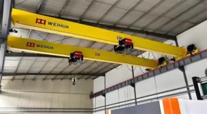
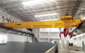
الرافعة الجسرية هي معدات رفع تُستخدم على نطاق واسع في مختلف الصناعات ومواقع البناء والموانئ والمستودعات وغيرها من المجالات. ويجعلها هيكلها الفريد وقدرتها القوية على تحمل الأحمال خيارًا مثاليًا لمناولة المواد الثقيلة في العصر الحديث. ويتيح تصميم الهيكل “الجسري” للرافعة التحرك بحرية داخل المساحة، مما يغطي منطقة عمل واسعة. إذن، ما الذي يجعل الرافعات الجسرية مميزة؟ وما هي أنواعها ومعاييرها وطرق التحكم فيها وتطبيقاتها ومبادئ عملها؟ كيف تختلف عن الرافعات الجسرية؟ دعونا نستكشف ذلك معًا. أنواع الرافعات الجسرية بناءً على التصميم والتطبيق وبيئة التشغيل، تُصنف الرافعات الجسرية عادةً إلى الأنواع التالية: الرافعة الجسرية أحادية العارضة تُستخدم الرافعات الجسرية أحادية العارضة على نطاق واسع في القطاعات الصناعية والمستودعات والموانئ وورش العمل. تتميز بآلية رفع مدعومة بعارضة واحدة، وتتحرك عبر أعمدة جانبية وقضبان سفلية. بفضل هيكلها البسيط وتشغيلها السهل وقدرتها المعتدلة على الرفع، فهي مثالية لمناولة الأحمال الخفيفة إلى المتوسطة. وبفضل قدرتها على عبور مسافات كبيرة بحرية، فإن الرافعات الجسرية ذات العارضة الواحدة مناسبة لعمليات مناولة ورفع المواد الثقيلة. الرافعات الجسرية ذات العارضتين مقارنة بالرافعات الجسرية ذات العارضة الواحدة، توفر الرافعات الجسرية ذات العارضتين قدرة أكبر...
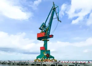
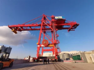
في الموانئ، والحدائق اللوجستية، ومناولة المواد الصناعية، تعتبر الرافعات البوابية والرافعات الجسرية نوعين شائعين وأساسيين من معدات التحميل/التفريغ. تختلف هذه الرافعات في التصميم الهيكلي، وخصائص الأداء، وطرق التشغيل، وسيناريوهات التطبيق، وتكاليف الاستثمار. تقدم هذه المقالة تحليلاً شاملاً للرافعات البوابية مقابل الرافعات الجسرية وتوجهك لاتخاذ الاختيار الصحيح. مقارنة التصميم الهيكلي تتجلى الاختلافات الهيكلية بين الرافعات البوابية والرافعات الجسرية بشكل أساسي في طرق تحمل الأحمال، ومسارات الحركة، ونطاقات التغطية. يركز الأول على برج ثابت وذراع دوار، مع التركيز على “تغطية النقاط” والدوران الأفقي المرن. يتميز الأخير ببنية إطار بوابة ورحلة سكة حديد طولية، مع إعطاء الأولوية لـ “الحركة الأفقية الواسعة” والتعامل الفعال مع الخدمات اللوجستية في الموقع. نتيجة لذلك، فإن تصميماتهما الهيكلية المميزة تملي مباشرة سيناريوهات التطبيق المختلفة. الخصائص الهيكلية للرافعات البوابية تستخدم الرافعات الدوارة البوابية هياكل أذرع مفردة/مزدوجة منصة، مع تثبيت البرج على الأسس أو السكك الحديدية، مما يتيح دورانًا بزاوية 360 درجة أو جزئيًا. يمكّن هذا التكوين التشغيل المرن في المساحات الضيقة والممتدة مثل السواحل، وواجهات الأرصفة، وأرصفة السفن، مما يجعله مناسبًا بشكل خاص لمناولة المواد من السفينة إلى الشاطئ. تجمع وظيفتها الأساسية بين العمودي…
في العمليات الصناعية الحديثة، تعتبر مناولة المواد الفعالة ضرورية لزيادة الإنتاجية وتحسين سير العمل. تعتبر الرافعات الجسرية، المعروفة أيضًا بالرافعات العلوية أو رافعات EOT، من أنظمة مناولة المواد الثابتة المستخدمة على نطاق واسع في التصنيع، ومعالجة المعادن، والتخزين، وعمليات التحميل/التفريغ. في هذه المقالة، سنستكشف مبدأ العمل، والمكونات الرئيسية، والتطبيقات، وفوائد التشغيل للرافعات الجسرية، مما يوفر دليلاً شاملاً للمخططين الصناعيين ومهنيي اللوجستيات. مبدأ عمل الرافعات الجسرية تعمل الرافعات الجسرية على هيكل يشبه الجسر يمتد عبر مساحة العمل، مع نظام عربة ورافعة يتحرك أفقيًا على طول الجسر ويرفع أو يخفض الأحمال عموديًا. تتيح حركة الرافعة عبر مسارها، جنبًا إلى جنب مع التحكم الدقيق بالرافعة، مناولة المواد الثقيلة بكفاءة وأمان في المصانع والمستودعات والمنشآت الصناعية. للحصول على معلومات حول كيفية عمل الرافعات العلوية، يرجى الاطلاع على هذه المقالة: مبدأ عمل الرافعات العلوية: المكونات، الحركة، وعملية التشغيل مصطلحات الرافعات الجسرية فيما يلي مقدمة للمصطلحات المتعلقة بأجزاء الرافعات الجسرية. سعة الرافعة: تشير سعة الرافعة إلى أقصى وزن يمكن للرافعة الجسرية رفعه بأمان. ويقاس عادة بالطن...
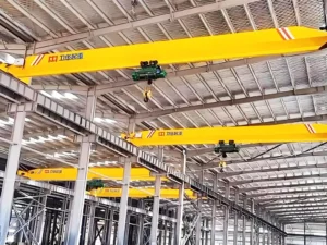
الرافعة العلوية الكهربائية (EOT) هي نظام رفع علوي فعال وموثوق يُستخدم لمناولة المواد الثقيلة في المصانع والمستودعات وورش العمل والمنشآت الصناعية. تعمل الرافعات العلوية الكهربائية على سكك علوية، وتتيح حركة ثلاثية الأبعاد آمنة ودقيقة للأحمال من خلال تنسيق حركات الرفع والتحرك العرضي والتحرك الطولي. ستوجهك هذه المقالة عبر تعريفات الرافعات العلوية المتحركة وأنواعها وهيكلها ومبادئ عملها وتطبيقاتها وعوامل التكلفة لمساعدتك في اختيار الحل الأنسب لاحتياجات الرفع الخاصة بك. كيف تعمل الرافعات العلوية المتحركة؟ يتضمن مبدأ عمل الرافعات العلوية المتحركة مزيجًا من الرفع الرأسي وحركة العربة الأفقية والحركة الطولية للجسر، مما يتيح مناولة الأحمال الثقيلة بكفاءة عبر المنشآت الصناعية. تعمل الرافعة على قضبان مسار مرتفعة مثبتة على طول هيكل المبنى، مع امتداد عارضة الجسر عبر مساحة العمل. تعمل آلية الرفع على رفع أو خفض الحمولة باستخدام حبال أو سلاسل سلكية فولاذية، بينما تقوم العربة بنقل الحمولة أفقيًا على طول الجسر. تتحرك الرافعة بأكملها طوليًا على طول قضبان المسار، مما يتيح وضع المواد في وضع ثلاثي الأبعاد. تعمل الرافعات الجسرية الكهربائية الحديثة بمحركات كهربائية ذات سرعة دقيقة...
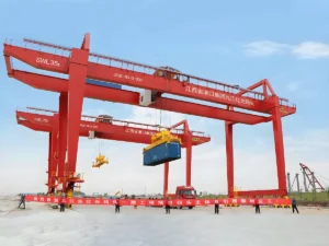
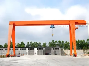
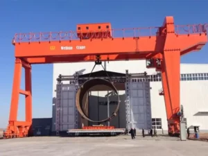
تُستخدم الرافعات الجسرية على نطاق واسع في ساحات التخزين المفتوحة، وأحواض بناء السفن، والمصانع، ومواقع البناء، مما يجعلها واحدة من أكثر حلول مناولة المواد تنوعًا وتطبيقًا على نطاق واسع. تأتي الرافعات الجسرية في أنواع مختلفة، وكل منها قابل للتخصيص ليناسب قدرات تحميل وسعات مختلفة، وظروف الموقع، ومتطلبات التشغيل. ومع ذلك، فإن اختيار التكوين الخاطئ يمكن أن يؤدي إلى نفقات غير ضرورية، أو قدرة رفع محدودة، أو قيود على التوسع المستقبلي. إذن، ما هي الأنواع الرئيسية للرافعات الجسرية؟ كيف تختار النوع المناسب لتطبيقك؟ في هذا الدليل، سنقدم نظرة عامة مفصلة على أنواع الرافعات الجسرية المختلفة بناءً على الهيكل، والتنقل، وسيناريوهات التطبيق، مما يساعدك على اتخاذ القرار الصحيح قبل الاستثمار في حل رفع. المقال طويل جدًا. فيما يلي جدول المحتويات الخاص بنا. يرجى التوجه إلى القسم المقابل حسب الحاجة: ما هي الرافعات الجسرية؟ الرافعات الجسرية هي معدات رفع مصممة لمناولة البضائع الثقيلة بكفاءة في المواقع المفتوحة الكبيرة. يتميز هيكلها المميز بشعاع أو أكثر من الأشعة الرئيسية مدعوم بأرجل صلبة (أو مرنة) على كلا الجانبين، لتشكيل إطار ضخم على شكل “بوابة”. تتنقل هذه الرافعات...
 English English
  Русский
 العربية
 Français
 Português
 Español