
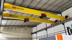
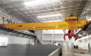
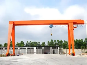
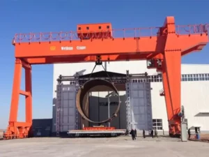








Here’s a problem procurement teams run into constantly: a project requires lifting a 120-ton component inside a partially built facility where no overhead crane exists, the floor is freshly poured concrete rated at 10 kN/m², and the work window is three weeks. A fixed gantry takes too long to install. A mobile truck crane can’t fit through the access corridor. What lifts the load?
A mobile hydraulic gantry crane is often the answer—and yet it’s one of the most misspecified pieces of lifting equipment in industrial procurement. Buyers focus on headline tonnage and miss the details that actually determine whether the crane performs safely and efficiently on their specific site. This guide covers the full picture: how hydraulic gantry cranes work, the three main configurations and when to use each, a detailed breakdown of the specification table, real application scenarios, and a practical checklist to use before you commit to a purchase order.
Table of Contents
How a Mobile Hydraulic Gantry Crane Actually Works
Before comparing models, it helps to understand what separates a hydraulic gantry crane from a conventional electric wire rope gantry. The distinction matters for both performance and maintenance planning.
In a standard electric gantry, a wire rope hoist drives the lift motion. Speed is stepped, load control is mechanical, and the system is relatively straightforward to maintain. In a hydraulic gantry, the lifting force comes from hydraulic cylinders powered by a hydraulic pump unit. Pressurized fluid extends or retracts the cylinders, raising or lowering the load with smooth, continuously variable speed control.
Why Hydraulic Power Changes the Lifting Equation
The hydraulic system delivers two capabilities that wire rope hoists struggle to match at heavy capacities.
First, synchronous multi-point lifting. When a load is too large or structurally sensitive to lift from a single point—a ship hull block, a bridge girder, a large industrial press—multiple hydraulic cylinders can be coupled and controlled together. The system maintains equal load distribution across all lift points within tight tolerances, typically ±2mm of height differential in precision applications. This level of control is not practical with independently operated wire rope hoists.
Second, load holding under power loss. Hydraulic cylinders are inherently self-locking when the control valve closes. If power is interrupted mid-lift, the load stays where it is. This is a meaningful safety characteristic for heavy industrial lifting where a suspended load dropping even a few centimeters can cause catastrophic damage.
The travel system works independently of the lifting mechanism. Wheeled units use electric or hydraulic motors driving rubber or steel wheels. The crane moves across the work surface between lifts, repositions over the load, extends outriggers or stabilizers, and then the hydraulic lifting cycle begins. The entire sequence—travel, position, stabilize, lift—can be managed by a single operator using a wireless remote control.
Three Configurations: Which Type Fits Your Operation?
.webp)
-scaled.webp)
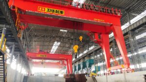
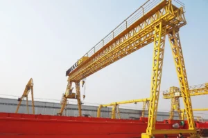
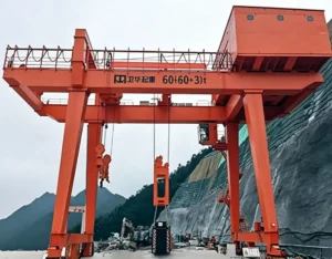
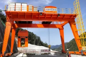
The mobile hydraulic gantry crane market divides into three structural configurations. Each solves a different site constraint. Choosing the wrong type adds cost without adding capability.
Wheel-Mounted Mobile Hydraulic Gantry Crane (WMHG Series)
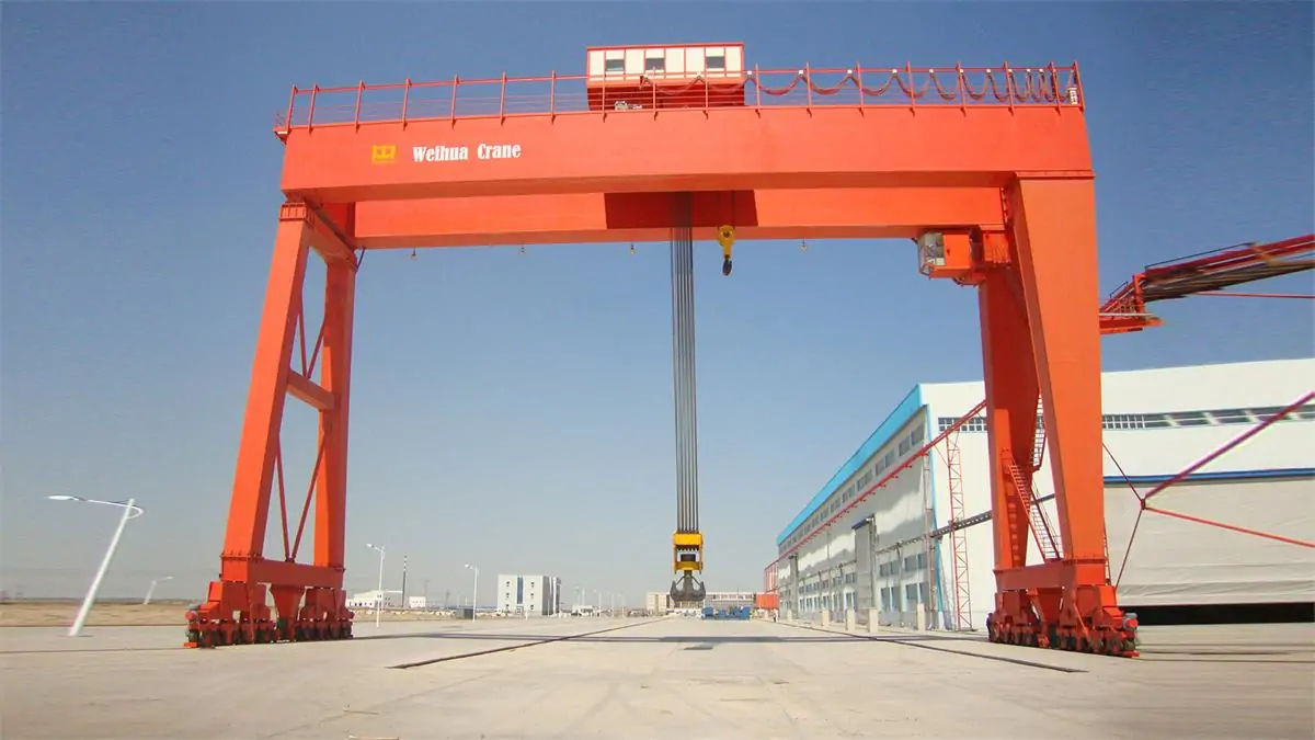
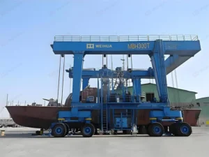
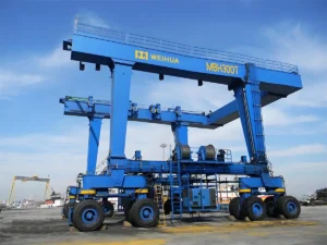
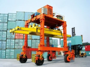
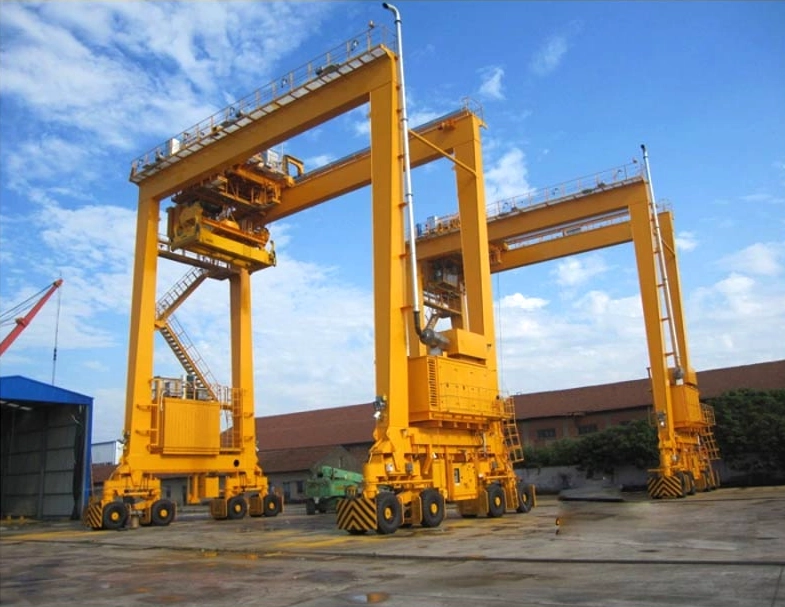
The WMHG series runs on rubber or steel wheels without any fixed track. It can travel freely across any flat, hard-surfaced work area—across a fabrication yard, through a warehouse, or between bays in a maintenance facility. This is the most widely deployed configuration because it combines meaningful load capacity with genuine site flexibility.
Typical operating parameters for WMHG units range from 10T to 500T rated capacity, spans from 5m to 16m, and lifting heights from 3m to 20m. The wheeled travel system requires a floor surface rated to handle the point loads transmitted through the outrigger pads. For a 100T unit, outrigger pad loads typically reach 25–40T per pad depending on configuration—confirm the specific values with your supplier and check them against your floor load rating before deployment.
Where it works best: Outdoor fabrication yards with compacted gravel or concrete surfaces, large warehouse facilities with reinforced floors, offshore module assembly areas, and any site where the crane needs to work in multiple locations without infrastructure investment.
Where it doesn’t work: Soft ground, significant slopes (typically limited to 1–2% max gradient for safe travel), or areas where floor load ratings cannot be confirmed.
Folding Mobile Hydraulic Gantry Crane (FHG Series)
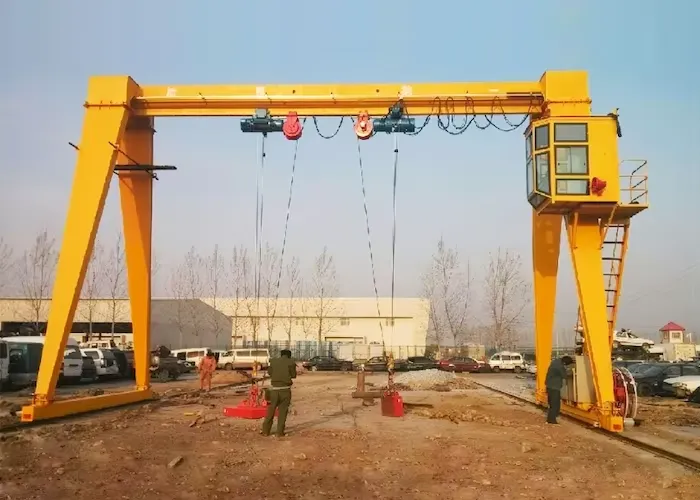
The FHG series is designed around transportability. The legs fold inward, reducing the crane’s footprint for loading onto a flatbed trailer or container. On-site assembly by a trained crew typically takes between 2 and 8 hours depending on crane size, compared to the multi-day installation required for larger fixed structures.
This portability makes the FHG series the natural choice for contractors who move equipment between project sites, field maintenance teams who need temporary heavy lift capability, or infrastructure maintenance operations where the crane might be needed at dozens of different locations over its working life.
The trade-off is capacity. Folding structural connections introduce complexity that limits practical capacity to roughly the 10T–100T range for most commercial FHG designs. For heavier lifts, the WMHG or RMG series is more appropriate.
Where it works best: Civil infrastructure maintenance (bridge beam replacement, culvert work), field machinery installation, project-based industrial maintenance where the crane relocates between jobs.
Where it doesn’t work: High-frequency repetitive lifting cycles (the folding joints require more regular inspection under sustained use), or applications requiring capacity above approximately 100T.
Rail-Mounted Mobile Hydraulic Gantry Crane (RMG Series)
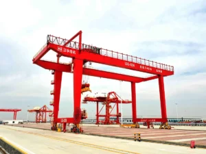
The RMG series travels on pre-installed steel rails rather than freely across a floor surface. The rails constrain the travel path but deliver two advantages: significantly higher lateral stability under eccentric or dynamic loads, and precise, repeatable positioning for production-line lifting operations.
In a shipyard running hull block assembly, for example, the same crane travels the same path dozens of times per week, lifting blocks of consistent geometry into defined positions. The rail system ensures the crane arrives at the same location within millimeter tolerances every cycle. That level of positional repeatability is difficult to achieve reliably with wheeled travel on a busy yard floor.
The civil work required to install and maintain rail tracks is the primary cost and commitment. For a temporary project or a facility with a changing layout, that investment doesn’t make sense. For a facility with a stable, high-volume production process, it pays back quickly in operational efficiency.
Where it works best: Shipyards, railway maintenance workshops, precast concrete segment plants, large-scale steel fabrication facilities with defined lifting corridors.
Where it doesn’t work: Sites where crane relocation flexibility is a regular operational requirement, or projects with a defined end date that doesn’t justify rail installation.
Specification Table: Reading the Numbers Correctly
The specification table below reflects the model range offered for industrial hydraulic gantry cranes. These parameters define the envelope of what each size class can do—and understanding them prevents the most common procurement mistakes.
| Model | Load Capacity | Span | Lifting Height | Power Source | Working Class | Operating Temp |
|---|---|---|---|---|---|---|
| MGL-10T | 10T | 5m | 3m | Electric Hydraulic | A5 | -20°C to +50°C |
| MGL-20T | 20T | 6m | 5m | Electric Hydraulic | A5 | -20°C to +50°C |
| MGL-50T | 50T | 8m | 8m | Diesel Engine | A4 | -10°C to +45°C |
| MGL-100T | 100T | 10m | 12m | Electric Hydraulic | A5 | -20°C to +50°C |
| MGL-200T | 200T | 12m | 15m | Electric Hydraulic | A4 | -20°C to +45°C |
| MGL-500T | 500T | 16m | 20m | Electric Hydraulic | A3 | -20°C to +40°C |
Working class per ISO 4301-1:2021. Confirm specific parameters with manufacturer documentation for your configuration.
Understanding Working Class: From A3 to A5 Explained
The working class column is frequently overlooked, but it directly affects both the crane’s structural design and its long-term maintenance cost. ISO 4301 classifies cranes from A1 (very light, infrequent use) through A8 (very heavy, continuous industrial use). A3 means the crane is designed for light-duty use with relatively few full-load cycles. A5 means it’s built for frequent operation at significant load fractions.
A 500T crane rated A3 is engineered for the number of lift cycles expected in a shipyard block lift application—heavy loads, but infrequent operations. A 10T crane rated A5 is built for the frequent cycle count of a busy maintenance workshop. Specifying a crane at a lower working class than your actual operation demands accelerates structural fatigue and increases the risk of unplanned downtime.
The Span-Capacity Relationship
A common mistake is treating the rated capacity as fixed regardless of span. It isn’t. As span increases, the bending moment on the main girder increases with it. Manufacturers rate their cranes at a specific span, and capacity may be derated at longer spans. If your application requires a 100T lift at a 14m span, you need to verify the crane’s rated capacity at that specific span—not just confirm the headline 100T figure.
Always request the load-span curve from the supplier and have your structural engineer review it against your specific application before purchase.
Where Mobile Hydraulic Gantry Cranes Deliver Real Value
Shipbuilding and Ship Repair
Shipyards represent the most demanding environment for hydraulic gantry cranes. Hull block assembly requires lifting steel sections weighing 100T to 500T or more, positioning them within tight tolerances against adjoining blocks, and holding them precisely while welding crews work below. The synchronous hydraulic lifting capability—holding multiple lift points at equal height within ±2mm—is not a convenience feature here. It’s a structural requirement. Uneven loading during block assembly can introduce permanent distortion into the hull structure.
Marine maintenance applications—engine removal, shaft replacement, rudder work—demand similar precision at lower capacities. The crane needs to lower heavy components into tight engine room spaces slowly, under full control, without sudden drops or shock loading.
Railway Maintenance Depots
Bogie exchange (replacing the wheel assembly under a locomotive or passenger car) is a repetitive, operationally critical task in railway maintenance. The crane must lift the car body, hold it level while the bogie is rolled out and a replacement rolled in, then lower the car body back onto the new assembly with enough precision to align the mounting interfaces correctly. Hydraulic gantry cranes handle this reliably. The smooth speed control during descent prevents the impact shock that can damage mounting surfaces and alignment features.
Industrial Construction and Module Installation
Large industrial facilities—refineries, power plants, processing plants—increasingly use modular construction methods where major equipment packages are assembled offsite and installed as complete units. A modular heat exchanger bundle might weigh 60–80T and need to be lowered into a structural bay from above. A mobile hydraulic gantry crane can straddle the installation bay, lift the module from a transport vehicle, and lower it precisely into position without the overhead obstruction that a fixed crane would create.
Customization Options Worth Knowing


Standard catalog configurations cover most applications, but hydraulic gantry cranes are routinely customized. The main variables that can be adjusted are:
- Lifting capacity: 10T to 500T in standard range; larger configurations available on inquiry
- Span: 5m to 16m standard; wider spans available with structural review
- Lifting height: up to 20m standard; taller configurations possible
- Power source: electric hydraulic for grid-connected sites; diesel for remote or outdoor applications; hybrid systems for sites with intermittent power
- Control system: pendant button, cab control, or wireless remote—wireless adds operator safety distance and flexibility
- Environmental specification: standard units rated to -20°C; arctic or high-temperature variants available
When specifying a custom configuration, document your requirements in writing before engaging the supplier. Include the maximum suspended load (with rigging), required span and lift height, floor load rating, available power supply, expected duty cycle, and any special environmental conditions. This prevents misunderstandings during the technical review and gives you a clear basis for comparing proposals.
Summary: What to Confirm Before You Order
A mobile hydraulic gantry crane is the right solution when you need heavy lift capability without permanent infrastructure, or when precise synchronous lifting is required across multiple points. Getting the specification right comes down to six parameters:
- Maximum suspended load including all rigging hardware—not just the product weight
- Span and lifting height at your specific work location
- Floor load rating and surface condition at all operating positions
- Working class matched to your actual lift frequency and load fraction
- Power source available or practical on your site
- Configuration type—wheeled for flexibility, folding for portability, rail-mounted for precision and stability
Define these six parameters clearly, request load-span curves from shortlisted suppliers, and compare proposals against your documented requirements rather than headline specifications. That process will eliminate most of the risk from what is, for most facilities, a significant capital decision.
FAQ
Q1: What is the maximum lifting capacity of a mobile hydraulic gantry crane?
Standard production models are available up to 500T, with the most common industrial configurations in the 50T–200T range. For applications above 500T, manufacturers can engineer custom solutions—some hydraulic gantry systems used in heavy module lifting for offshore and shipbuilding applications reach 1,000T and beyond by coupling multiple units. The key is that capacity must always be confirmed at your specific operating span, not just as a standalone figure. A crane rated 200T at a 12m span may carry a lower rating at a 14m span due to increased bending loads on the main girder.
Q2: How do I know if my floor can support a mobile hydraulic gantry crane?
The critical figure is the point load transmitted through each outrigger pad to the floor surface. For a 100T crane, typical outrigger pad loads range from 25T to 40T per pad depending on configuration—your floor needs to be rated above this figure with an appropriate safety margin. Standard industrial concrete floors (200mm slab, C30 concrete) typically carry 8–12 kN/m², which is sufficient for most medium-duty units with properly sized outrigger pads. For soft ground or unrated surfaces, spread mats or temporary ground reinforcement are standard practice. Always request the outrigger load data from your supplier and have your civil engineer confirm floor adequacy before deployment.
Q3: What maintenance does a hydraulic gantry crane require, and how often?
Maintenance centers on three areas. The hydraulic system requires fluid sampling every 500–1,000 operating hours to check for contamination and degradation, filter replacement per manufacturer schedule (typically every 500 hours for A4–A5 duty applications), and visual inspection of hoses, seals, and cylinder surfaces before each shift. The structural components—welds, pins, leg connections, and main girder—should be inspected annually by a qualified engineer, with interim checks after any abnormal loading event. The travel system (wheels, bearings, drive motors) follows the manufacturer’s lubrication and inspection schedule. Establishing a service agreement with the supplier or a certified crane maintenance provider from commissioning is strongly recommended for any unit operating at A4 or A5 working class.
Q4: Can one operator run a mobile hydraulic gantry crane alone?
Yes, for most standard lifting operations. Wireless remote control allows a single operator to manage travel, positioning, outrigger extension, and hydraulic lifting from a safe distance with clear sightlines to the load. For complex lifts—multi-point synchronous lifts of large structures, or lifts in congested areas with limited visibility—a second person acting as a signal person (banksman) is standard safe practice regardless of control system capability. Local regulations on minimum crew requirements vary by jurisdiction and crane class; verify the applicable requirements in your region before planning staffing.
Q5: How long does installation take for a mobile hydraulic gantry crane on a new site?
Folding series (FHG) units designed for portability can be assembled and ready for operation in 2–8 hours by a trained crew of 2–4 people. Wheeled units (WMHG) in the 50T–200T range typically require 1–2 days for assembly, leveling, and hydraulic pre-operation checks. Rail-mounted units (RMG) require additional time for rail installation if not already in place—this is a civil works scope that should be planned and budgeted separately. For any first deployment on a new site, add time for floor load verification, operator familiarization, and a no-load trial run before commencing production lifts. Request a detailed commissioning procedure from your supplier as part of the purchase package.