- ProductEquipmentPrecision Power, Customization Crane SolutionE-mail:WhatsApp / Wechat:+8613781917315Address:No.18 Shanhai Road, Changyuan City, Henan Province, China


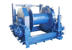
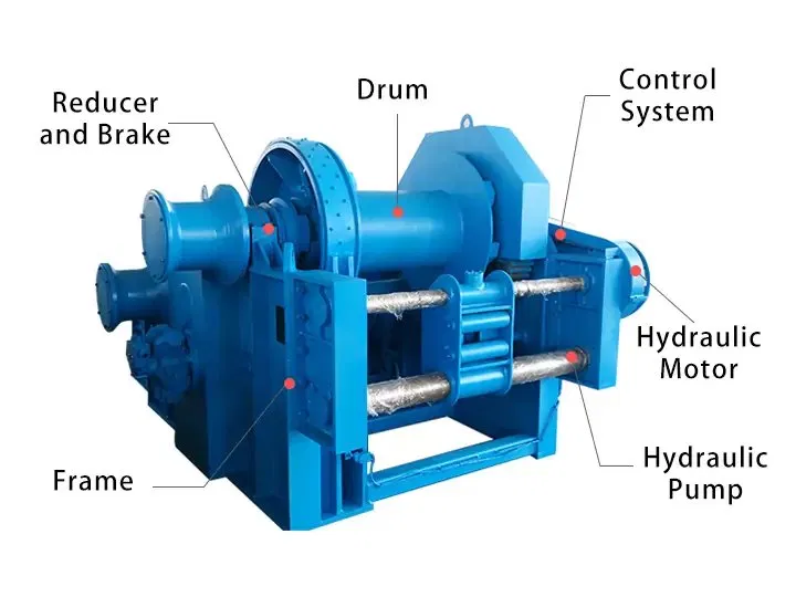
A hydraulic winch is a powered mechanical device that converts hydraulic energy into rotational force to wind a steel wire rope onto a drum, generating the pulling or lifting force required to move, anchor, or position heavy loads. The hydraulic motor receives pressurized fluid from an external hydraulic power unit (HPU) or the host machine’s existing hydraulic system, eliminating the need for a separate electrical power supply at the winch location.
The defining characteristics of a hydraulic winch — compared to an electric winch of equivalent rated capacity — are its ability to operate at full torque from zero speed, sustain continuous duty cycles without overheating, maintain precise control at very low line speeds, and stall safely under overload without mechanical damage. These properties make the hydraulic winch the standard solution for marine mooring and anchor handling, offshore platform operations, mining haulage, oilfield pipe-laying, and heavy construction work where electric power is unavailable, unreliable, or insufficient.
The term hydraulic winches refers to the broader product family covering all capacity ranges, mounting configurations, and application types. Whether the application requires a compact 1 t mooring winch or a 100 t offshore towing winch, the core operating principle — hydraulic motor driving a geared drum through a fail-safe brake — is consistent across the full product range of hydraulic winches available from Weihua.
Weihua hydraulic winches are classified by drum structure. Selecting the correct configuration depends on the number of independent rope lines required, the need for synchronized lifting, and the total load capacity of the application.
A single-drum hydraulic winch uses one drum driven by a hydraulic motor to wind and unwind a single wire rope for lifting or pulling operations. The overall structure is straightforward, controls are simple, and the unit is easy to install and maintain. Single-drum hydraulic winches cover the full capacity range from 1 t to 100 t and are the standard configuration for the majority of marine, construction, mining, and industrial traction applications.
Typical applications: Ship mooring and anchor handling, construction site pulling, inclined shaft haulage, offshore deck winches, pipeline and cable laying.
A double-drum hydraulic winch is equipped with two independent or mechanically interlinked drum systems, each driven by its own hydraulic motor or by a shared drive with clutch separation. The two drums can operate synchronously — for balanced lifting of a single load across two rope lines — or independently, controlling two separate loads or rope paths simultaneously. Compared to a single-drum configuration, the double-drum hydraulic winch provides greater total lifting capacity, effective load balancing across the lift points, and more precise control in multi-point lifting and positioning operations.
Typical applications: Heavy marine crane hoisting systems, offshore platform equipment handling requiring balanced two-point lift, large ship mooring systems with independent fore and aft lines, synchronized cable-laying operations.
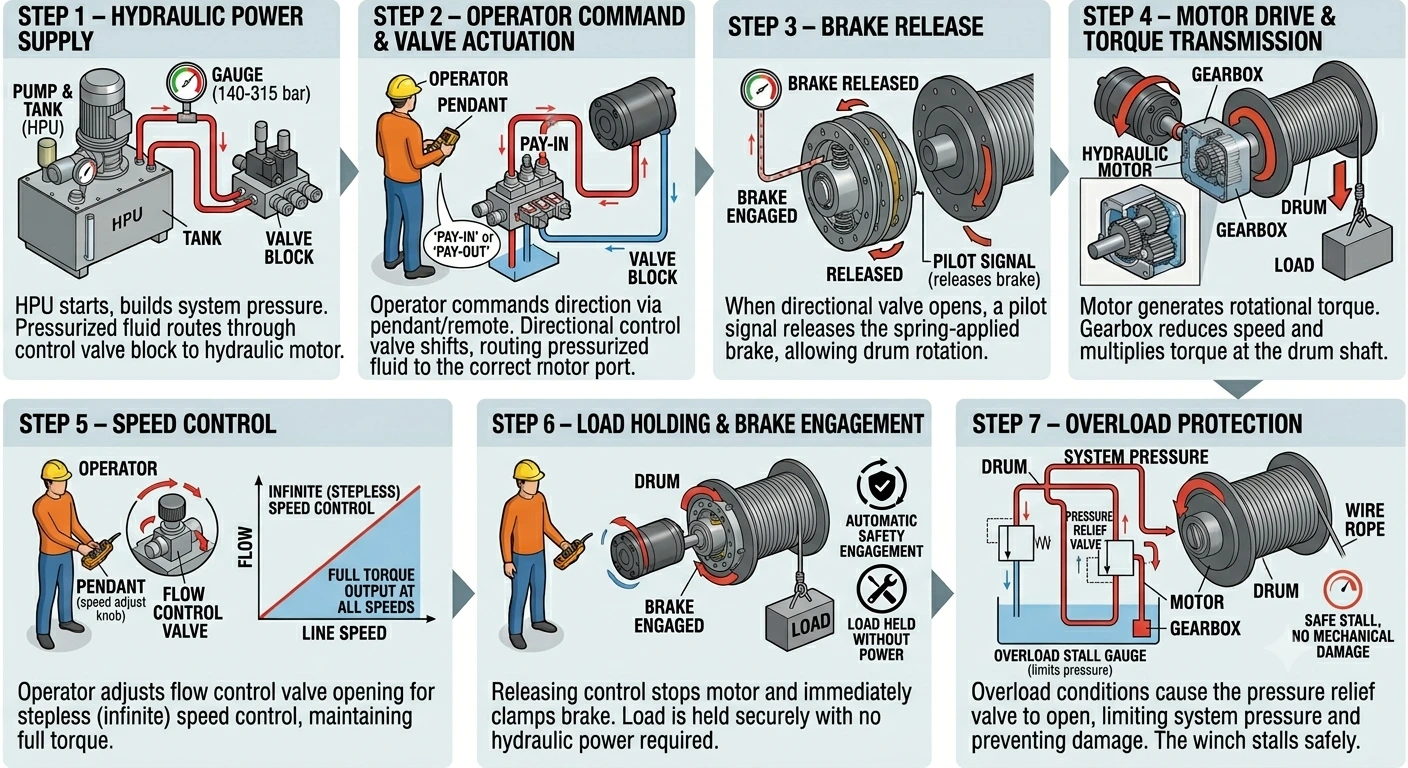
Step 1 — Hydraulic Power Supply The hydraulic power unit starts and builds system pressure to the working pressure specified for the winch model (140–315 bar depending on capacity). Pressurized hydraulic fluid is routed through the control valve block to the hydraulic motor.
Step 2 — Operator Command & Valve Actuation The operator commands pay-in (drum wind) or pay-out (drum unwind) via the pendant control or remote system. The directional control valve in the valve block shifts, routing pressurized fluid to the appropriate port of the hydraulic motor and returning low-pressure fluid to the tank.
Step 3 — Brake Release When the directional valve opens and system pressure builds, a pilot signal releases the spring-applied brake, allowing the drum to rotate. The brake remains released for as long as the operator holds the command and system pressure is maintained.
Step 4 — Motor Drive & Torque Transmission High-pressure fluid drives the hydraulic motor, generating rotational torque. The gearbox reduces motor speed and multiplies torque at the drum shaft, providing the pulling force required to wind the wire rope and lift or pull the rated load at the specified line speed.
Step 5 — Speed Control The operator adjusts the flow control valve opening to vary the hydraulic fluid flow rate to the motor, providing stepless (infinite) speed control from near-zero to maximum line speed. Unlike an electric winch, which requires a variable frequency drive for speed control, the hydraulic winch achieves full stepless control through the hydraulic valve alone, maintaining full torque output at any speed including very low speeds.
Step 6 — Load Holding & Brake Engagement When the operator releases the control, the directional valve closes, motor rotation stops, and the spring-applied brake immediately clamps the drum. The load is held securely at its current position with no drift, and no hydraulic power is required to maintain the hold. In the event of hydraulic pressure loss, the brake engages automatically and the load remains locked.
Step 7 — Overload Protection If the wire rope tension exceeds the winch’s rated pulling capacity — due to a snagged load or unexpected resistance — the pressure relief valve in the hydraulic circuit opens, limiting system pressure and preventing damage to the motor, gearbox, drum, and wire rope. The winch stalls safely without overheating or mechanical failure, a key advantage over electric winches in overload conditions.
| Capacity (t) | Line Pull (kN) | Wire Rope Diameter (mm) | Drum Capacity (m) | Working Pressure (bar) | Line Speed (m/min) |
|---|---|---|---|---|---|
| 1 – 2 | 10 – 20 | 12 – 16 | 50 – 100 | 140 – 160 | 15 – 25 |
| 3 – 5 | 30 – 50 | 16 – 22 | 80 – 150 | 160 – 180 | 12 – 20 |
| 8 – 10 | 80 – 100 | 24 – 28 | 100 – 200 | 180 – 200 | 10 – 18 |
| 15 – 20 | 150 – 200 | 28 – 36 | 150 – 300 | 200 – 250 | 8 – 15 |
| 30 – 50 | 300 – 500 | 40 – 52 | 200 – 400 | 250 – 280 | 6 – 12 |
| 60 – 100 | 600 – 1000 | 56 – 76 | 300 – 600 | 280 – 315 | 5 – 10 |
Choosing between a hydraulic winch and an electric winch depends on the application’s load, duty cycle, environment, and available power infrastructure. The table below covers the primary decision factors.
| Factor | Hydraulic Winch | Electric Winch |
|---|---|---|
| Drive system | Hydraulic motor + HPU | Electric motor + gearbox |
| Speed control | Stepless via flow control valve | Stepped contactor or VFD |
| Torque at zero speed | Full rated torque | Lower; requires VFD for low-speed torque |
| Continuous duty | Yes — oil circuit dissipates heat | Duty cycle limited by motor thermal rating |
| Overload behavior | Stalls safely via relief valve | Motor trips or overheats |
| Brake type | Spring-applied, hydraulic released (fail-safe) | Electromagnetic (spring-applied optional) |
| Explosion-proof | Intrinsically safe at winch head | Full Ex enclosure required at motor |
| Power requirement | Hydraulic supply (HPU or host system) | 3-phase electrical supply |
| Low-speed stability | Excellent — smooth at near-zero speed | Limited without high-quality VFD |
| Unit weight | Lower for equivalent capacity | Higher for equivalent capacity |
| Maintenance | Hydraulic oil, seals, filters | Electrical components, motor windings |
| Suitable environment | Harsh, marine, offshore, mining, hazardous | General industrial, indoor |
For applications in standard indoor industrial environments with reliable electrical supply and moderate duty cycles, an electric winch is often the simpler and more economical choice. For heavy loads, continuous duty, marine and offshore service, hazardous areas, or where electrical power is unavailable, a hydraulic winch is the correct solution.
1. Rated Pulling Capacity The rated pulling capacity of a hydraulic winch is specified at the first layer of rope on the drum. As rope builds up on the drum in multiple layers, the effective drum radius increases and the pulling force decreases. If your application requires the full rated capacity at the end of a long rope run, confirm the multi-layer performance with our engineering team and select a model with sufficient first-layer capacity.
2. Wire Rope Diameter and Drum Capacity Rope diameter must be matched to the rated pulling capacity and the minimum breaking load of the rope selected. Drum capacity (in meters) must be sufficient to cover the full rope travel required by the application, including any dead wraps retained on the drum at maximum pay-out.
3. Line Speed Requirement Line speed affects both operational productivity and the hydraulic flow rate required from the HPU. Higher line speeds require greater hydraulic flow. Confirm that the HPU or host hydraulic system can supply the required flow at the working pressure of the selected winch model.
4. Working Pressure and HPU Compatibility Hydraulic winch models are designed to operate within a specific working pressure range (140–315 bar). The HPU must supply pressure within this range at the required flow rate. If integrating the winch into an existing machine hydraulic system, confirm that system pressure and available flow are compatible with the winch specification before ordering.
5. Mounting Configuration Hydraulic winches are available in base-plate (horizontal), flange-mount, and vertical drum configurations. Confirm the available mounting space, deck loading capacity, and required rope lead direction before specifying the mounting arrangement.
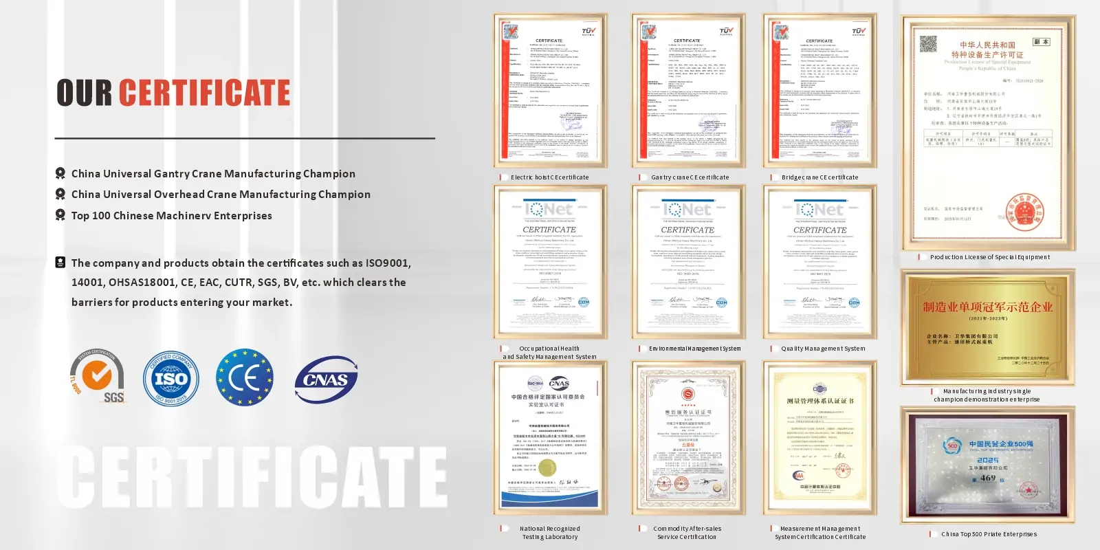
6. Certification Requirements Marine applications require classification society certification (ABS, CCS, DNV, BV, or LR depending on vessel flag state). Offshore and hazardous area applications may require ATEX or IECEx explosion-proof certification for the HPU and control system. Mining applications require Mine Safety Certification. Specify the required certifications at the time of inquiry to ensure the correct documentation is provided with delivery.
| Certification / Standard | Coverage |
|---|---|
| CE Marking | European conformity — Machinery Directive 2006/42/EC |
| ISO 9001 | Quality management system |
| ABS (American Bureau of Shipping) | Marine and offshore — US and international flag vessels |
| CCS (China Classification Society) | Marine and offshore — China flag vessels and domestic market |
| DNV (Det Norske Veritas) | Marine and offshore — Norwegian and international flag vessels |
| BV (Bureau Veritas) | Marine and offshore — French and international flag vessels |
| LR (Lloyd’s Register) | Marine and offshore — UK and international flag vessels |
| ATEX / IECEx | Explosion-proof HPU and controls for Zone 1 / Zone 2 hazardous areas |
| Mine Safety Certificate | Underground mining and coal industry applications |
Classification society and explosion-proof certification is available on request for applicable models. Certification documentation is provided with delivery and supports vessel class surveys, facility compliance audits, and regulatory inspections.
Weihua is a professional hydraulic winch manufacturer and supplier based in China, with over 37 years of experience in lifting and traction equipment design and manufacturing. All Weihua hydraulic winches are produced under a rigorous quality management system certified to ISO 9001, and every unit is CE-marked in compliance with the European Machinery Directive.
Weihua provides a global after-sales service network, a one-year product warranty, and long-term spare parts availability for all hydraulic winch models. Our engineering team supports custom winch specifications, hydraulic system integration, and on-site installation and commissioning for marine, offshore, mining, and construction projects worldwide.
We also offer a comprehensive range of lifting and material handling equipment, including electric winches, overhead cranes, gantry cranes, and wire rope hoists. Contact our engineering team today for a customized hydraulic winch solution — or browse our full range of hydraulic winches for sale and request a quotation directly.
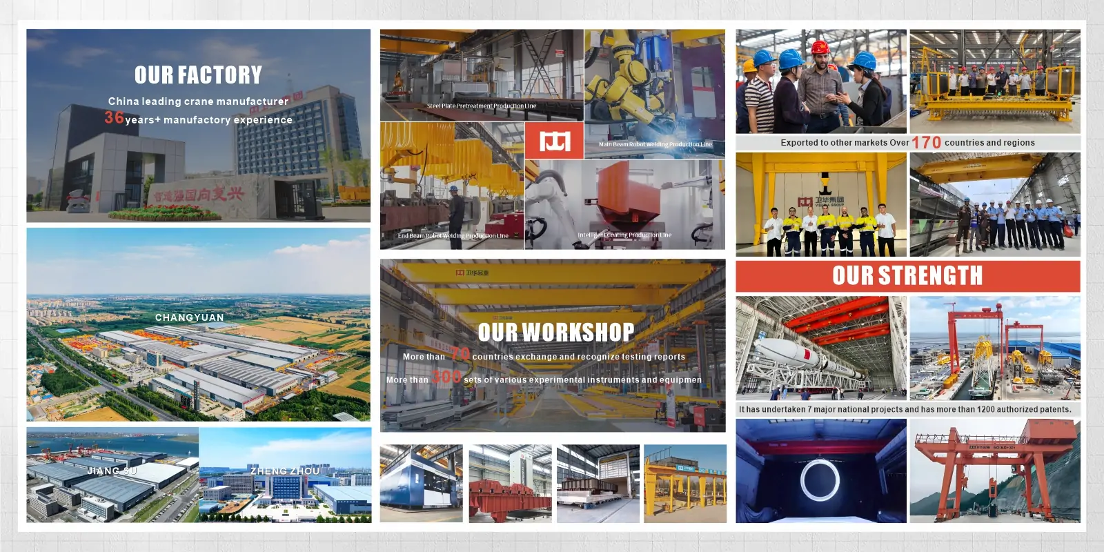
Weihua, founded in 1988, has evolved into a global leader in China's intelligent manufacturing field. We specialize in smart crane R&D and production while offering AGV solutions. Our professional engineering, delivery, and after-sales teams provide one-stop technical support, customized solutions, on-site installation guidance, and rapid-response global services to ensure every project operates safely and efficiently.
A hydraulic winch is a powered traction device that uses pressurized hydraulic fluid to drive a motor, which rotates a drum to wind and unwind a steel wire rope. The wire rope transmits pulling or lifting force to the load. Hydraulic winches are used wherever heavy loads must be moved, lifted, anchored, or positioned in demanding industrial, marine, mining, or construction environments.
A hydraulic winch is powered by pressurized hydraulic fluid from a hydraulic power unit or host machine hydraulic system. An electric winch is powered by a three-phase electrical supply. Hydraulic winches deliver higher torque, better low-speed control, continuous duty capability, and inherent explosion-proof compatibility at the winch head. Electric winches are simpler to install where reliable electrical power is available and duty cycles are moderate. For heavy, continuous, or hazardous-area applications, a hydraulic winch is the correct choice.
A hydraulic power unit supplies pressurized fluid to a hydraulic motor mounted on the winch. The motor converts fluid pressure into rotational torque, which passes through a gearbox to the wire rope drum. As the drum rotates, the wire rope winds onto or off the drum, generating pulling or lifting force. A spring-applied brake locks the drum automatically whenever the hydraulic circuit is depressurized or the operator releases the control, holding the load at any position without hydraulic power.
Working pressure depends on the winch model and rated capacity. Weihua hydraulic winches operate in the range of 140 bar (for 1–2 t models) to 315 bar (for 60–100 t models). The hydraulic power unit must supply the specified working pressure at the required flow rate for the selected line speed.
A hydraulic winch contains no electrical components at the winch body. This makes the winch itself intrinsically compatible with hazardous environments, since there is no electrical arc or heat source at the winch location. For Zone 1 or Zone 2 classified areas, the hydraulic power unit and control system require ATEX or IECEx certification. This arrangement is simpler and less costly than certifying a fully electric winch and motor for explosion-proof service.
Contact us now via email: [email protected], or fill in the form below.


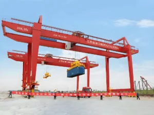
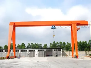
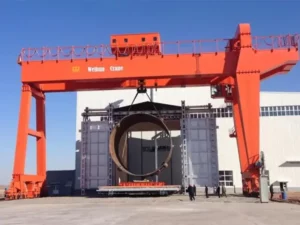
The gantry crane is a lifting equipment widely used across various industries, construction sites, ports, warehouses, and other fields. Its unique structure and powerful load-bearing capacity make it ideal for modern heavy-duty material handling. The “gantry” structure design allows the crane to move freely within a space, covering a large working area. So, what makes gantry cranes special? What are their types, parameters, control methods, applications, and working principles? How do they differ from bridge cranes? Let’s explore together. Types of Gantry Cranes Based on design, application, and operating environment, gantry cranes are typically categorized into the following types: Single-Girder Gantry Crane Single-girder gantry cranes are widely used across industrial sectors, warehouses, ports, and workshops. Featuring a single-girder support lifting mechanism, they traverse via side columns and bottom rails. With their simple structure, user-friendly operation, and moderate lifting capacity, they are ideal for handling light to medium loads. Capable of spanning large distances freely, single-girder gantry cranes are suitable for heavy material handling and lifting operations. Double Girder Gantry Crane Compared to single-girder gantry cranes, double-girder gantry cranes offer greater…
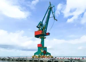
In ports, logistics parks, and industrial material handling, Portal Cranes and Gantry Cranes are two common and core loading/unloading equipment types. They differ in structural design, performance characteristics, operating methods, application scenarios, and investment costs. This article provides a comprehensive analysis of Portal Crane vs Gantry Crane and guides you in making the right selection. Structural Design Comparison The structural differences between Portal Cranes and Gantry Cranes primarily manifest in load-bearing methods, movement trajectories, and coverage ranges. The former centers on a fixed tower and rotating boom, emphasizing “point coverage” and flexible horizontal rotation. The latter features a portal frame structure and longitudinal rail travel, prioritizing “extensive horizontal movement” and efficient on-site logistics handling. Consequently, their distinct structural designs directly dictate their differing application scenarios. Portal Crane Structural Characteristics Portal slewing cranes employ single/double cantilever boom structures with the tower fixed to foundations or rails, enabling 360° or partial rotation. This configuration enables flexible operation in narrow, elongated spaces such as shorelines, dock fronts, and ship berths, making it particularly suitable for ship-to-shore material handling. Its core functionality combines vertical…
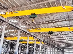
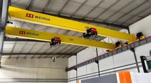
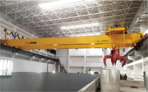
In modern industrial operations, efficient material handling is crucial for maximizing productivity and optimizing workflow. Bridge cranes, also known as overhead cranes or EOT cranes, are fixed material handling systems widely used in manufacturing, metal processing, warehousing, and loading/unloading operations. In this article, we will explore the working principle, main components, applications, and operational benefits of bridge cranes, providing a comprehensive guide for industrial planners and logistics professionals. Bridge Crane Working Principle A bridge crane operates on a bridge-like structure spanning the workspace, with a trolley and hoist system that moves horizontally along the bridge and vertically lifts or lowers loads. The crane’s movement across the runway, combined with precise hoist control, enables efficient and safe handling of heavy materials in factories, warehouses, and industrial facilities. For information on how overhead cranes work, please see this article: Overhead Crane Working Principle: Components, Motion & Operating Process Bridge Crane Terminology The following is an introduction to terminology related to bridge crane parts. Crane Capacity: Crane capacity refers to the maximum weight a bridge crane can safely lift. Typically measured in tons…
An EOT Crane (Electric Overhead Traveling Crane) is an efficient and reliable overhead lifting system used to handle heavy materials in factories, warehouses, workshops, and industrial plants. Running on overhead rails, EOT cranes enable safe and precise three-dimensional movement of loads through coordinated lifting, cross travel, and long travel motions. This article will guide you through EOT crane definitions, types, structure, working principles, applications, and cost factors to help you select the most suitable solution for your lifting needs. How EOT Crane Works? The working principle of an EOT crane involves a combination of vertical lifting, horizontal trolley movement, and longitudinal bridge travel, enabling efficient handling of heavy loads across industrial facilities. The crane operates on elevated runway rails installed along the building structure, with the bridge girder spanning the workspace. The hoist mechanism raises or lowers the load using steel wire ropes or chains, while the trolley moves the load horizontally along the bridge. The entire crane travels longitudinally along the runway rails, enabling three-dimensional positioning of materials. Modern EOT cranes are powered by electric motors with precise speed…
Gantry cranes are widely used in open-air stockyards, shipyards, factories, and construction sites, making them one of the most versatile and extensively applied material handling solutions. Gantry cranes come in various types, each customizable to suit different load capacities, site conditions, and operational requirements. However, selecting the wrong configuration can lead to unnecessary expenses, limited lifting capacity, or future expansion constraints. So, what are the main types of gantry cranes? How do you choose the right type for your application? In this guide, we will provide a detailed overview of different types of gantry cranes based on structure, mobility, and application scenarios, helping you make the right decision before investing in a lifting solution. The article is quite lengthy. Below is our table of contents. Please jump to the corresponding section as needed: What Is a Gantry Crane? Gantry cranes are lifting equipment designed for efficient handling of heavy cargo in large open-air sites. Their signature structure features one or more main beams supported by rigid (or flexible) legs on either side, forming a monumental “gate”-shaped frame. These cranes traverse…
 English English
  Русский
 العربية
 Français
 Português
 Español