- ProdutoEquipamentoPrecisão de Potência, Personalização Solução de GruaCorreio eletrónico:WhatsApp / Wechat:+8613781917315Morada:N.º 18 Shanhai Road, Changyuan City, Província de Henan, China


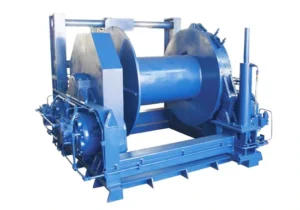
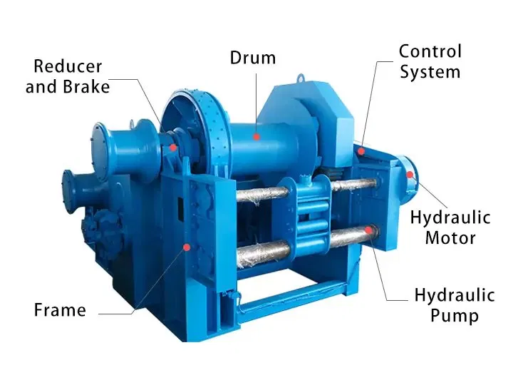
A hydraulic winch is a powered mechanical device that converts hydraulic energy into rotational force to wind a steel wire rope onto a drum, generating the pulling or lifting force required to move, anchor, or position heavy loads. The hydraulic motor receives pressurized fluid from an external hydraulic power unit (HPU) or the host machine’s existing hydraulic system, eliminating the need for a separate electrical power supply at the winch location.
The defining characteristics of a hydraulic winch — compared to an electric winch of equivalent rated capacity — are its ability to operate at full torque from zero speed, sustain continuous duty cycles without overheating, maintain precise control at very low line speeds, and stall safely under overload without mechanical damage. These properties make the hydraulic winch the standard solution for marine mooring and anchor handling, offshore platform operations, mining haulage, oilfield pipe-laying, and heavy construction work where electric power is unavailable, unreliable, or insufficient.
The term hydraulic winches refers to the broader product family covering all capacity ranges, mounting configurations, and application types. Whether the application requires a compact 1 t mooring winch or a 100 t offshore towing winch, the core operating principle — hydraulic motor driving a geared drum through a fail-safe brake — is consistent across the full product range of hydraulic winches available from Weihua.
Weihua hydraulic winches are classified by drum structure. Selecting the correct configuration depends on the number of independent rope lines required, the need for synchronized lifting, and the total load capacity of the application.
A single-drum hydraulic winch uses one drum driven by a hydraulic motor to wind and unwind a single wire rope for lifting or pulling operations. The overall structure is straightforward, controls are simple, and the unit is easy to install and maintain. Single-drum hydraulic winches cover the full capacity range from 1 t to 100 t and are the standard configuration for the majority of marine, construction, mining, and industrial traction applications.
Typical applications: Ship mooring and anchor handling, construction site pulling, inclined shaft haulage, offshore deck winches, pipeline and cable laying.
A double-drum hydraulic winch is equipped with two independent or mechanically interlinked drum systems, each driven by its own hydraulic motor or by a shared drive with clutch separation. The two drums can operate synchronously — for balanced lifting of a single load across two rope lines — or independently, controlling two separate loads or rope paths simultaneously. Compared to a single-drum configuration, the double-drum hydraulic winch provides greater total lifting capacity, effective load balancing across the lift points, and more precise control in multi-point lifting and positioning operations.
Typical applications: Heavy marine crane hoisting systems, offshore platform equipment handling requiring balanced two-point lift, large ship mooring systems with independent fore and aft lines, synchronized cable-laying operations.
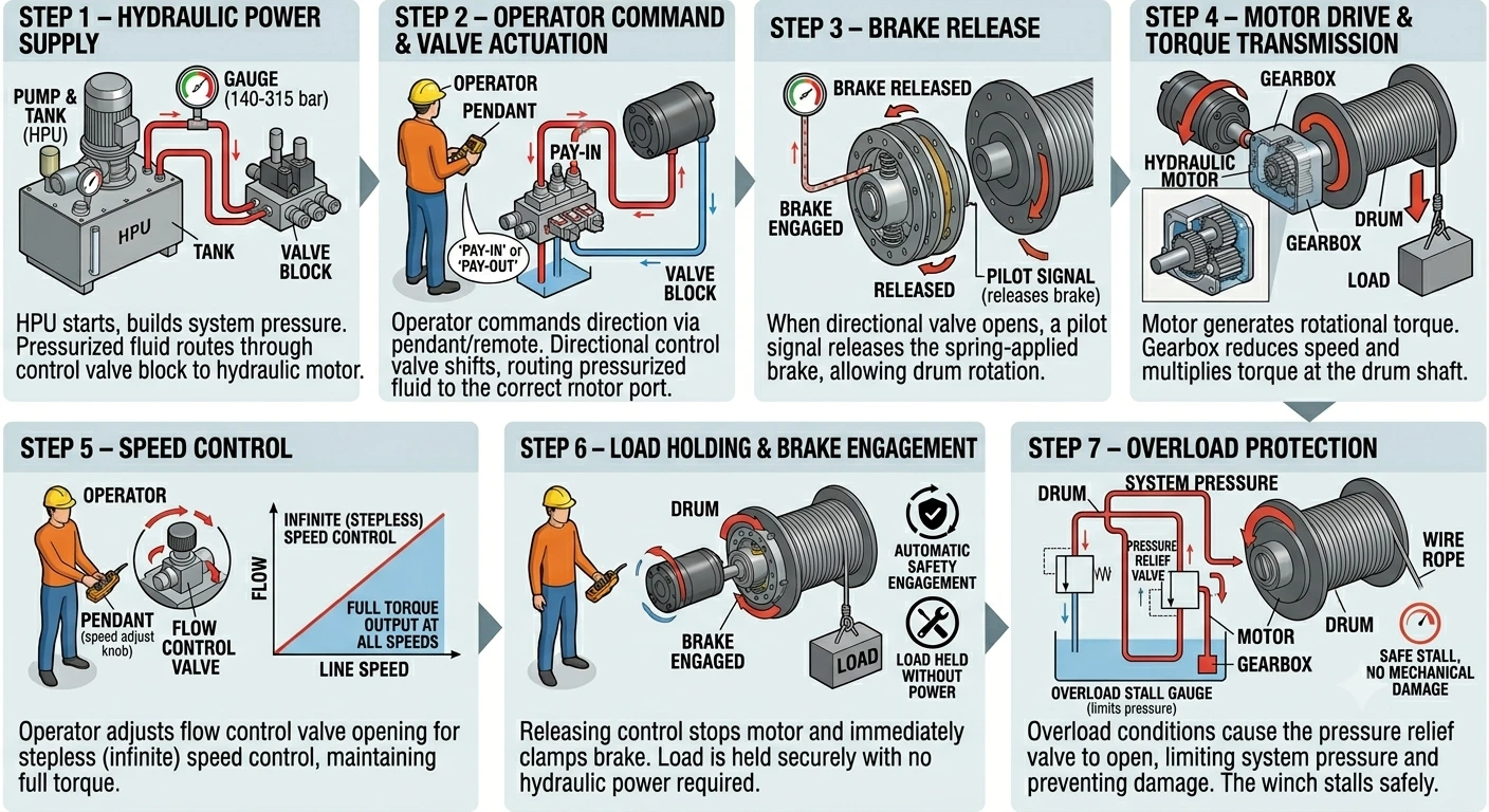
Step 1 — Hydraulic Power Supply The hydraulic power unit starts and builds system pressure to the working pressure specified for the winch model (140–315 bar depending on capacity). Pressurized hydraulic fluid is routed through the control valve block to the hydraulic motor.
Step 2 — Operator Command & Valve Actuation The operator commands pay-in (drum wind) or pay-out (drum unwind) via the pendant control or remote system. The directional control valve in the valve block shifts, routing pressurized fluid to the appropriate port of the hydraulic motor and returning low-pressure fluid to the tank.
Step 3 — Brake Release When the directional valve opens and system pressure builds, a pilot signal releases the spring-applied brake, allowing the drum to rotate. The brake remains released for as long as the operator holds the command and system pressure is maintained.
Step 4 — Motor Drive & Torque Transmission High-pressure fluid drives the hydraulic motor, generating rotational torque. The gearbox reduces motor speed and multiplies torque at the drum shaft, providing the pulling force required to wind the wire rope and lift or pull the rated load at the specified line speed.
Step 5 — Speed Control The operator adjusts the flow control valve opening to vary the hydraulic fluid flow rate to the motor, providing stepless (infinite) speed control from near-zero to maximum line speed. Unlike an electric winch, which requires a variable frequency drive for speed control, the hydraulic winch achieves full stepless control through the hydraulic valve alone, maintaining full torque output at any speed including very low speeds.
Step 6 — Load Holding & Brake Engagement When the operator releases the control, the directional valve closes, motor rotation stops, and the spring-applied brake immediately clamps the drum. The load is held securely at its current position with no drift, and no hydraulic power is required to maintain the hold. In the event of hydraulic pressure loss, the brake engages automatically and the load remains locked.
Step 7 — Overload Protection If the wire rope tension exceeds the winch’s rated pulling capacity — due to a snagged load or unexpected resistance — the pressure relief valve in the hydraulic circuit opens, limiting system pressure and preventing damage to the motor, gearbox, drum, and wire rope. The winch stalls safely without overheating or mechanical failure, a key advantage over electric winches in overload conditions.
| Capacity (t) | Line Pull (kN) | Wire Rope Diameter (mm) | Drum Capacity (m) | Working Pressure (bar) | Line Speed (m/min) |
|---|---|---|---|---|---|
| 1 – 2 | 10 – 20 | 12 – 16 | 50 – 100 | 140 – 160 | 15 – 25 |
| 3 – 5 | 30 – 50 | 16 – 22 | 80 – 150 | 160 – 180 | 12 – 20 |
| 8 – 10 | 80 – 100 | 24 – 28 | 100 – 200 | 180 – 200 | 10 – 18 |
| 15 – 20 | 150 – 200 | 28 – 36 | 150 – 300 | 200 – 250 | 8 – 15 |
| 30 – 50 | 300 – 500 | 40 – 52 | 200 – 400 | 250 – 280 | 6 – 12 |
| 60 – 100 | 600 – 1000 | 56 – 76 | 300 – 600 | 280 – 315 | 5 – 10 |
Choosing between a hydraulic winch and an electric winch depends on the application’s load, duty cycle, environment, and available power infrastructure. The table below covers the primary decision factors.
| Factor | Guincho hidráulico | Electric Winch |
|---|---|---|
| Drive system | Hydraulic motor + HPU | Electric motor + gearbox |
| Speed control | Stepless via flow control valve | Stepped contactor or VFD |
| Torque at zero speed | Full rated torque | Lower; requires VFD for low-speed torque |
| Continuous duty | Yes — oil circuit dissipates heat | Duty cycle limited by motor thermal rating |
| Overload behavior | Stalls safely via relief valve | Motor trips or overheats |
| Brake type | Spring-applied, hydraulic released (fail-safe) | Electromagnetic (spring-applied optional) |
| Explosion-proof | Intrinsically safe at winch head | Full Ex enclosure required at motor |
| Power requirement | Hydraulic supply (HPU or host system) | 3-phase electrical supply |
| Low-speed stability | Excellent — smooth at near-zero speed | Limited without high-quality VFD |
| Unit weight | Lower for equivalent capacity | Higher for equivalent capacity |
| Manutenção | Hydraulic oil, seals, filters | Electrical components, motor windings |
| Suitable environment | Harsh, marine, offshore, mining, hazardous | General industrial, indoor |
For applications in standard indoor industrial environments with reliable electrical supply and moderate duty cycles, an electric winch is often the simpler and more economical choice. For heavy loads, continuous duty, marine and offshore service, hazardous areas, or where electrical power is unavailable, a hydraulic winch is the correct solution.
1. Rated Pulling Capacity The rated pulling capacity of a hydraulic winch is specified at the first layer of rope on the drum. As rope builds up on the drum in multiple layers, the effective drum radius increases and the pulling force decreases. If your application requires the full rated capacity at the end of a long rope run, confirm the multi-layer performance with our engineering team and select a model with sufficient first-layer capacity.
2. Wire Rope Diameter and Drum Capacity Rope diameter must be matched to the rated pulling capacity and the minimum breaking load of the rope selected. Drum capacity (in meters) must be sufficient to cover the full rope travel required by the application, including any dead wraps retained on the drum at maximum pay-out.
3. Line Speed Requirement Line speed affects both operational productivity and the hydraulic flow rate required from the HPU. Higher line speeds require greater hydraulic flow. Confirm that the HPU or host hydraulic system can supply the required flow at the working pressure of the selected winch model.
4. Working Pressure and HPU Compatibility Hydraulic winch models are designed to operate within a specific working pressure range (140–315 bar). The HPU must supply pressure within this range at the required flow rate. If integrating the winch into an existing machine hydraulic system, confirm that system pressure and available flow are compatible with the winch specification before ordering.
5. Mounting Configuration Hydraulic winches are available in base-plate (horizontal), flange-mount, and vertical drum configurations. Confirm the available mounting space, deck loading capacity, and required rope lead direction before specifying the mounting arrangement.
6. Certification Requirements Marine applications require classification society certification (ABS, CCS, DNV, BV, or LR depending on vessel flag state). Offshore and hazardous area applications may require ATEX or IECEx explosion-proof certification for the HPU and control system. Mining applications require Mine Safety Certification. Specify the required certifications at the time of inquiry to ensure the correct documentation is provided with delivery.
| Certification / Standard | Coverage |
|---|---|
| Marcação CE | European conformity — Machinery Directive 2006/42/EC |
| ISO 9001 | Quality management system |
| ABS (American Bureau of Shipping) | Marine and offshore — US and international flag vessels |
| CCS (China Classification Society) | Marine and offshore — China flag vessels and domestic market |
| DNV (Det Norske Veritas) | Marine and offshore — Norwegian and international flag vessels |
| BV (Bureau Veritas) | Marine and offshore — French and international flag vessels |
| LR (Lloyd’s Register) | Marine and offshore — UK and international flag vessels |
| ATEX / IECEx | Explosion-proof HPU and controls for Zone 1 / Zone 2 hazardous areas |
| Mine Safety Certificate | Underground mining and coal industry applications |
Classification society and explosion-proof certification is available on request for applicable models. Certification documentation is provided with delivery and supports vessel class surveys, facility compliance audits, and regulatory inspections.
Weihua is a professional hydraulic winch manufacturer and supplier based in China, with over 37 years of experience in lifting and traction equipment design and manufacturing. All Weihua hydraulic winches are produced under a rigorous quality management system certified to ISO 9001, and every unit is CE-marked in compliance with the European Machinery Directive.
Weihua provides a global after-sales service network, a one-year product warranty, and long-term spare parts availability for all hydraulic winch models. Our engineering team supports custom winch specifications, hydraulic system integration, and on-site installation and commissioning for marine, offshore, mining, and construction projects worldwide.
We also offer a comprehensive range of lifting and material handling equipment, including electric winches, overhead cranes, gantry cranes, and wire rope hoists. Contact our engineering team today for a customized hydraulic winch solution — or browse our full range of hydraulic winches for sale and request a quotation directly.
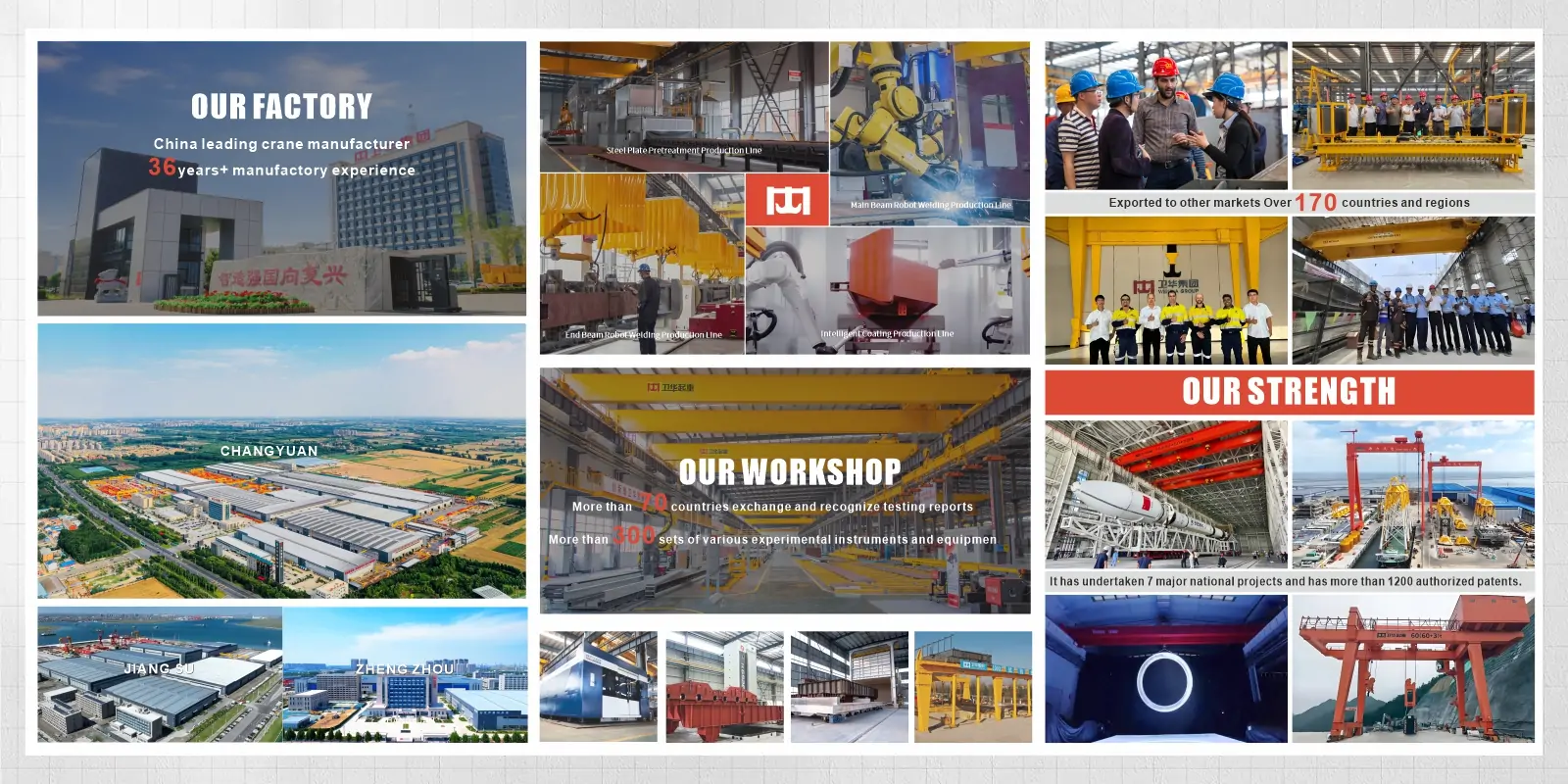
Fundada em 1988, a Weihua evoluiu para uma líder global no campo da manufatura inteligente na China. Somos especializados em I&D e produção de gruas inteligentes, ao mesmo tempo que oferecemos soluções AGV. As nossas equipas profissionais de engenharia, entrega e pós-venda fornecem suporte técnico multifacetado, soluções personalizadas, orientação de instalação no local e serviços globais de resposta rápida para garantir que cada projeto opere de forma segura e eficiente.
A hydraulic winch is a powered traction device that uses pressurized hydraulic fluid to drive a motor, which rotates a drum to wind and unwind a steel wire rope. The wire rope transmits pulling or lifting force to the load. Hydraulic winches are used wherever heavy loads must be moved, lifted, anchored, or positioned in demanding industrial, marine, mining, or construction environments.
A hydraulic winch is powered by pressurized hydraulic fluid from a hydraulic power unit or host machine hydraulic system. An electric winch is powered by a three-phase electrical supply. Hydraulic winches deliver higher torque, better low-speed control, continuous duty capability, and inherent explosion-proof compatibility at the winch head. Electric winches are simpler to install where reliable electrical power is available and duty cycles are moderate. For heavy, continuous, or hazardous-area applications, a hydraulic winch is the correct choice.
A hydraulic power unit supplies pressurized fluid to a hydraulic motor mounted on the winch. The motor converts fluid pressure into rotational torque, which passes through a gearbox to the wire rope drum. As the drum rotates, the wire rope winds onto or off the drum, generating pulling or lifting force. A spring-applied brake locks the drum automatically whenever the hydraulic circuit is depressurized or the operator releases the control, holding the load at any position without hydraulic power.
Working pressure depends on the winch model and rated capacity. Weihua hydraulic winches operate in the range of 140 bar (for 1–2 t models) to 315 bar (for 60–100 t models). The hydraulic power unit must supply the specified working pressure at the required flow rate for the selected line speed.
A hydraulic winch contains no electrical components at the winch body. This makes the winch itself intrinsically compatible with hazardous environments, since there is no electrical arc or heat source at the winch location. For Zone 1 or Zone 2 classified areas, the hydraulic power unit and control system require ATEX or IECEx certification. This arrangement is simpler and less costly than certifying a fully electric winch and motor for explosion-proof service.
Contacte-nos agora por email: [email protected], ou preencha o formulário abaixo.


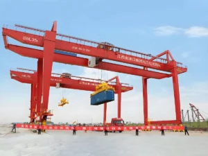
O pórtico rolante é um equipamento de elevação amplamente utilizado em diversos setores industriais, locais de construção, portos, armazéns e outros campos. A sua estrutura única e a sua potente capacidade de suporte de carga tornam-no ideal para a manipulação moderna de materiais de alta resistência. O design da estrutura do “pórtico” permite que o guindaste se mova livremente num espaço, cobrindo uma grande área de trabalho. Então, o que torna os pórticos rolantes especiais? Quais são os seus tipos, parâmetros, métodos de controlo, aplicações e princípios de funcionamento? Como diferem dos pontes rolantes? Vamos explorar juntos. Tipos de Pórtico Rolante Com base no design, aplicação e ambiente de operação, os pórticos rolantes são tipicamente categorizados nos seguintes tipos: Pórtico Rolante de Viga Única Os pórticos rolantes de viga única são amplamente utilizados em setores industriais, armazéns, portos e oficinas. Apresentando um mecanismo de elevação de suporte de viga única, eles percorrem através de colunas laterais e calhas inferiores. Com a sua estrutura simples, operação fácil de usar e capacidade de elevação moderada, são ideais para manusear cargas leves a médias. Capazes de cobrir grandes distâncias livremente, os pórticos rolantes de viga única são adequados para operações de elevação e manuseio de materiais pesados. Pórtico Rolante de Viga Dupla Em comparação com os pórticos rolantes de viga única, os pórticos rolantes de viga dupla oferecem maior…
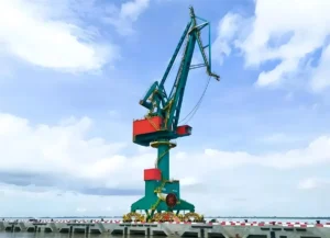
Nos portos, parques logísticos e manuseamento de materiais industriais, as Gruas Pórtico e as Gruas de Portão são dois tipos comuns e essenciais de equipamentos de carga/descarga. Diferem no design estrutural, características de desempenho, métodos de operação, cenários de aplicação e custos de investimento. Este artigo fornece uma análise abrangente da comparação entre Gruas Pórtico e Gruas de Portão e orienta-o na escolha correta. Comparação do Design Estrutural As diferenças estruturais entre Gruas Pórtico e Gruas de Portão manifestam-se principalmente nos métodos de suporte de carga, trajetórias de movimento e alcances de cobertura. A primeira foca-se numa torre fixa e numa lança rotativa, enfatizando a “cobertura de ponto” e a rotação horizontal flexível. A última apresenta uma estrutura de portal e movimento longitudinal sobre carris, priorizando o “movimento horizontal extenso” e o manuseamento eficiente de logística no local. Consequentemente, os seus designs estruturais distintos ditam diretamente os seus diferentes cenários de aplicação. Características Estruturais da Grua Pórtico As gruas giratórias tipo pórtico empregam estruturas de lança de um ou dois cantiléveres com a torre fixada a fundações ou carris, permitindo uma rotação de 360° ou parcial. Esta configuração permite uma operação flexível em espaços estreitos e alongados, como linhas costeiras, frentes de cais e berços de navios, tornando-a particularmente adequada para o manuseamento de materiais entre navio e terra. A sua funcionalidade principal combina verticalmente…
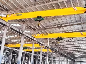
Nas operações industriais modernas, a movimentação eficiente de materiais é crucial para maximizar a produtividade e otimizar o fluxo de trabalho. Os pontes rolantes, também conhecidos como gruas aéreas ou gruas EOT, são sistemas fixos de manuseio de materiais amplamente utilizados em operações de fabrico, processamento de metais, armazenamento e operações de carga/descarga. Neste artigo, exploraremos o princípio de funcionamento, os componentes principais, as aplicações e os benefícios operacionais das pontes rolantes, fornecendo um guia abrangente para planeadores industriais e profissionais de logística. Princípio de Funcionamento da Ponte Rolante Uma ponte rolante opera numa estrutura semelhante a uma ponte que abrange o espaço de trabalho, com um carro e um sistema de elevação que se move horizontalmente ao longo da ponte e levanta ou baixa cargas verticalmente. O movimento da ponte rolante na via, combinado com o controlo preciso do elevação, permite o manuseio eficiente e seguro de materiais pesados em fábricas, armazéns e instalações industriais. Para informações sobre como funcionam as gruas aéreas, consulte este artigo: Princípio de Funcionamento das Gruas Aéreas: Componentes, Movimento e Processo Operacional Terminologia da Ponte Rolante Segue-se uma introdução à terminologia relacionada com as partes da ponte rolante. Capacidade da Ponte Rolante: A capacidade da ponte rolante refere-se ao peso máximo que uma ponte rolante pode levantar em segurança. Geralmente medida em toneladas...
Uma Ponte Rolante EOT (Electric Overhead Traveling Crane) é um sistema de elevação aéreo eficiente e fiável, utilizado para manusear materiais pesados em fábricas, armazéns, oficinas e instalações industriais. Correndo sobre carris suspensos, as pontes rolantes EOT permitem o movimento tridimensional seguro e preciso de cargas, através de movimentos coordenados de elevação, translação transversal e translação longitudinal. Este artigo irá guiá-lo através das definições, tipos, estrutura, princípios de funcionamento, aplicações e fatores de custo das pontes rolantes EOT, para o ajudar a selecionar a solução mais adequada às suas necessidades de elevação. Como funciona uma Ponte Rolante EOT? O princípio de funcionamento de uma ponte rolante EOT envolve uma combinação de elevação vertical, movimento horizontal do carro e movimento longitudinal da ponte, permitindo o manuseamento eficiente de cargas pesadas em instalações industriais. A ponte rolante opera em carris de pista elevados, instalados ao longo da estrutura do edifício, com a viga da ponte a cobrir o espaço de trabalho. O mecanismo de elevação sobe ou desce a carga utilizando cabos de aço ou correntes, enquanto o carro move a carga horizontalmente ao longo da ponte. A ponte rolante inteira desloca-se longitudinalmente ao longo dos carris da pista, permitindo o posicionamento tridimensional dos materiais. As pontes rolantes EOT modernas são acionadas por motores elétricos com velocidade precisa…
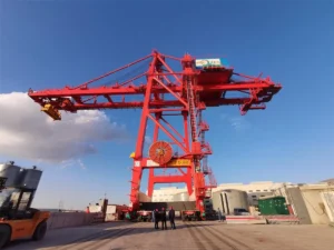
As gruas porta-pórtico são amplamente utilizadas em pátios de estocagem ao ar livre, estaleiros, fábricas e locais de construção, tornando-as uma das soluções de manuseio de materiais mais versáteis e extensivamente aplicadas. As gruas porta-pórtico vêm em vários tipos, cada uma personalizável para se adequar a diferentes capacidades de carga, condições do local e requisitos operacionais. No entanto, a seleção da configuração errada pode levar a despesas desnecessárias, capacidade de elevação limitada ou restrições de expansão futuras. Então, quais são os principais tipos de gruas porta-pórtico? Como escolher o tipo certo para a sua aplicação? Neste guia, forneceremos uma visão geral detalhada dos diferentes tipos de gruas porta-pórtico com base na estrutura, mobilidade e cenários de aplicação, ajudando-o a tomar a decisão certa antes de investir numa solução de elevação. O artigo é bastante longo. Abaixo está o nosso índice. Por favor, salte para a secção correspondente, conforme necessário: O que é uma Grua Porta-Pórtico? As gruas porta-pórtico são equipamentos de elevação concebidos para o manuseio eficiente de cargas pesadas em grandes locais ao ar livre. A sua estrutura distinta apresenta uma ou mais vigas principais suportadas por pernas rígidas (ou flexíveis) de cada lado, formando uma estrutura monumental em forma de “portão”. Estas gruas atravessam…
 English English
  Русский
 العربية
 Français
 Português
 Español